
Wax pattern injection molding apparatus and method for casting articles using the wax pattern injection molding apparatus

A technology of injection molding device and wax mold, which is used in casting molding equipment, cores, casting molds, etc.

Active Publication Date: 2018-11-13
EISHIN GIKEN
View PDF12 Cites 0 Cited by
  • Summary
  • Abstract
  • Description
  • Claims
  • Application Information

AI Technical Summary

Problems solved by technology

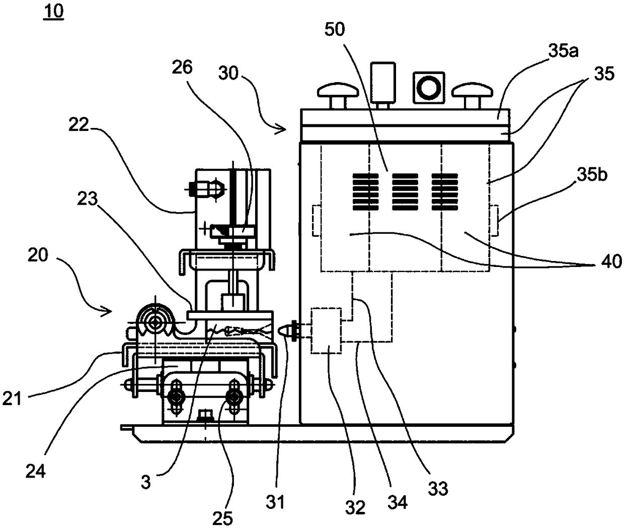
Therefore, the rubber mold 3 has to be pressed against the injection nozzle 31 until the time required for the wax inside the runner to solidify

Method used


Image

  • Wax pattern injection molding apparatus and method for casting articles using the wax pattern injection molding apparatus
  • Wax pattern injection molding apparatus and method for casting articles using the wax pattern injection molding apparatus
  • Wax pattern injection molding apparatus and method for casting articles using the wax pattern injection molding apparatus

Examples


no. 1 Embodiment approach

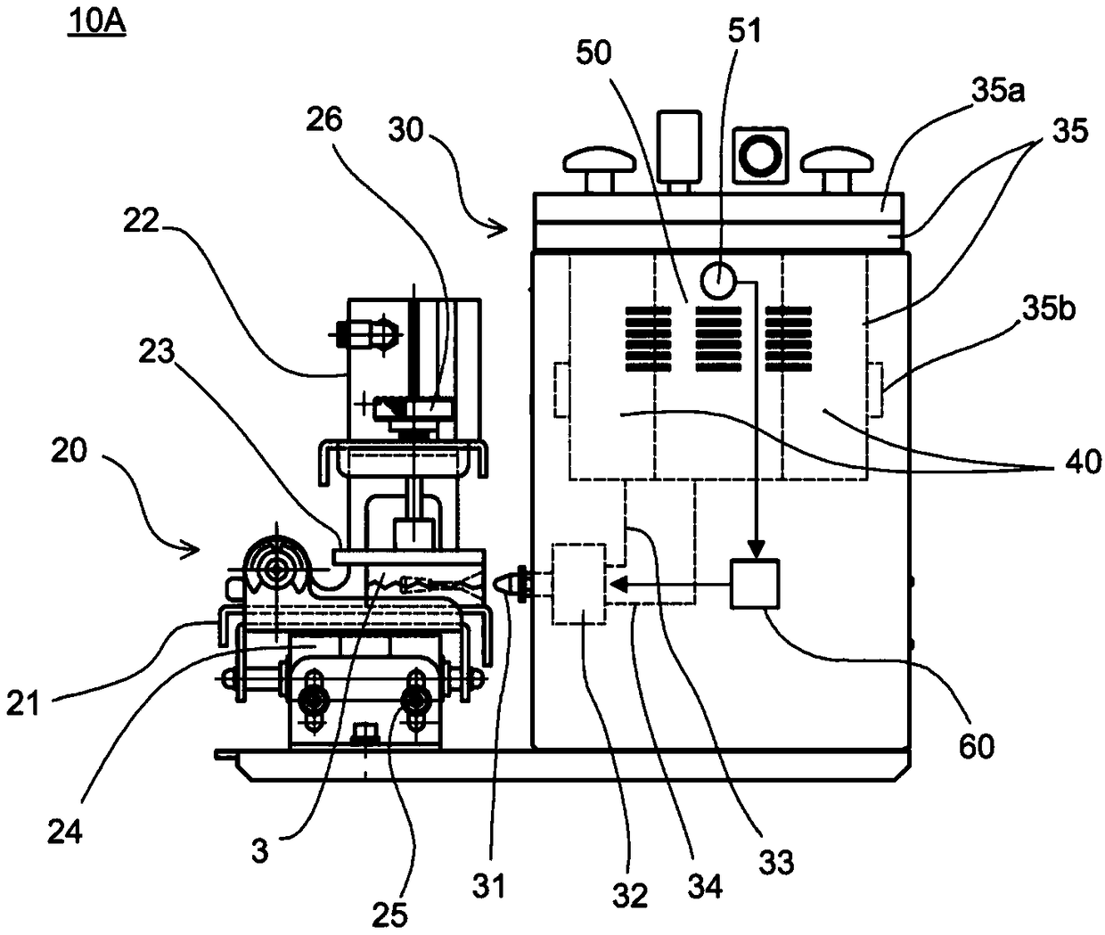
[0127] The wax pattern injection molding apparatus 10A of the present embodiment includes a clamp unit 20 , a wax injection unit 30 , and an operation control unit 60 . The clamp unit 20 and the wax injection unit 30 basically have the same structure as the clamp unit 20 and the wax injection unit 30 of the wax mold injection molding apparatus 10 .

[0128] Figure 4 The vacuum tank 50 of the wax injection unit 30 of this embodiment is shown.

[0129] As shown in the figure, a pressure sensor 51 and a vacuum pump 52 are connected to the vacuum chamber 50 . The pressure sensor 51 is used to measure the pressure (air pressure) inside the vacuum tank 50 . The pressure sensor 51 can be any device, structure, or structure that can measure the pressure inside the vacuum chamber 50 . The pressure sensor 51 can be, for example, a vacuum gauge such as a Pirani vacuum gauge, a MacLeod vacuum gauge, or a liquid column vacuum gauge.

[0130] The injection nozzle 31 is connected to the...

Embodiment approach 1-2

[0172] In Embodiment 1-2, the operation control unit 60 controls wax injection based on the pressure P of the vacuum chamber 50 . In a preferred embodiment, the action control unit 60 controls the time from the start of wax injection (for example, the moment when the switching mechanism 32 is switched from state 2 to state 3) to the end of wax injection (for example, the moment when the switching mechanism 32 is switched from state 3 to state 3). State 1 switching moment) this period (called wax injection time Ti) is controlled. In a particularly preferred embodiment, the operation control unit 60 calculates the cavity volume Vg from the pressure P of the vacuum chamber 50, and determines the wax injection time Ti based on the cavity volume Vg. The operation control unit 60 can switch the mechanism 32 from the state 3 to the state 1 after the elapse of time Ti from the time when the switching mechanism 32 is switched from the state 2 to the state 3 .

[0173] The case where t...

no. 2 Embodiment approach

[0185] The vacuum valve 54 of the wax pattern injection molding apparatus 10A can be omitted. Alternatively, the wax injection molding apparatus 10A may be used without opening and closing control with the vacuum valve 54 opened. This embodiment is referred to as a second embodiment.


PUM

PropertyMeasurementUnit
melting pointaaaaaaaaaa

Abstract

The present invention is open to the vacuum and / or wax injection of the device to shorten the operation time and / or the wax mold injection molding device (10A) that can be shortened by the device and / or the quality of the wax mold (10A) and the use of the wax mold injection molding device (10A) Casting method of items.The wax mold injection molding device (10A) has: vacuum groove (50); nozzle (31), which connects to the vacuum groove (50); and the pressure sensor (51), which is used to measure the vacuum groove (50 50) Pressure; the wax mold injection molding device (10A) can use the nozzle (31) to use the vacuum groove (50) of the mold (3) of the mold (3)(3) Performing wax injection.Action control components (60) control the pumping vacuum and / or wax injection based on the pressure (P) of the vacuum groove (50).In the preferred embodiment, the motion control component (60) controls the vacuum and / or the wax injection of the vacuum and / or the wax injection based on the vacuum groove (50) pressure (P) pressure (p)Implementation time.

Description

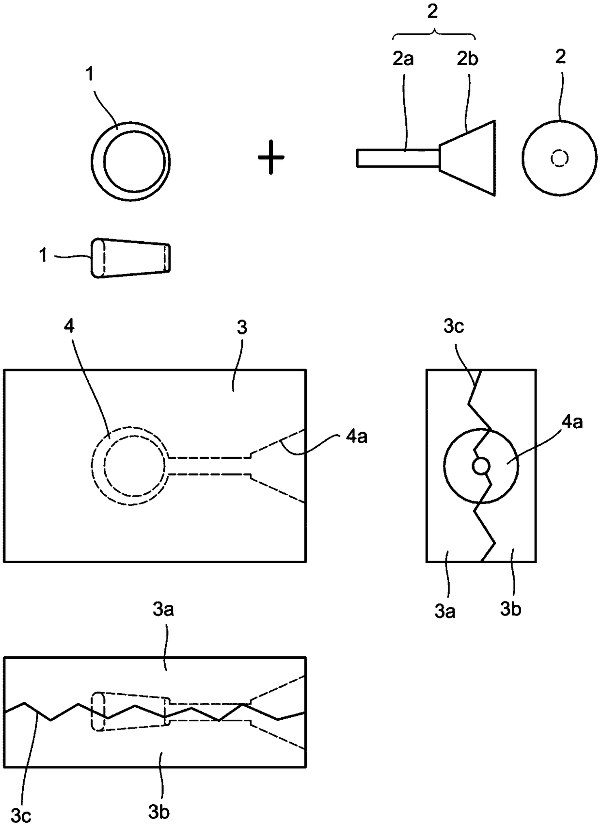
technical field [0001] The present application relates to a wax injection molding apparatus used in lost wax casting and a method of casting articles using the wax injection molding apparatus. Background technique [0002] Ornaments, accessories, jewels, etc. that mainly use precious metals have small, complicated, and precise shapes. There is a need to produce such products in large quantities and in this industry the lost wax investment casting method is well developed. Of course, the lost-wax precision casting method can also be applied to the manufacture of precision industrial parts other than the above. [0003] Lost wax investment casting in the jewelry manufacturing industry has the following steps. [0004] The first process is a process of making a prototype. [0005] The second step is to make a rubber mold with a cavity having the same shape as the prototype. [0006] The third step is to inject melted wax into the rubber mold and take out the wax to make a w...

Claims


Application Information

Patent Timeline
Patent Type & Authority Patents(China)
IPC IPC(8): B22C9/04B22C7/02B29C45/64B29C45/76
CPCB22C7/02B22C9/04B29K2091/00B29C67/241
Inventor 久保几营
Owner EISHIN GIKEN
Learn More