Circuit assembly for high-voltage tests and high-voltage testing system

A technology of circuit device and high voltage test, which is applied in the direction of test circuit, measuring device, transformer test, etc., can solve the problem of high cost and achieve the effect of eliminating cost and cost

Inactive Publication Date: 2017-09-26
SIEMENS ENERGY GLOBAL GMBH CO & KG
View PDF11 Cites 3 Cited by
  • Summary
  • Abstract
  • Description
  • Claims
  • Application Information

AI Technical Summary

Problems solved by technology

Testing of gas-insulated products such as gas-insulated switchgear is particularly costly

Method used


Image

  • Circuit assembly for high-voltage tests and high-voltage testing system
  • Circuit assembly for high-voltage tests and high-voltage testing system

Examples


Embodiment Construction

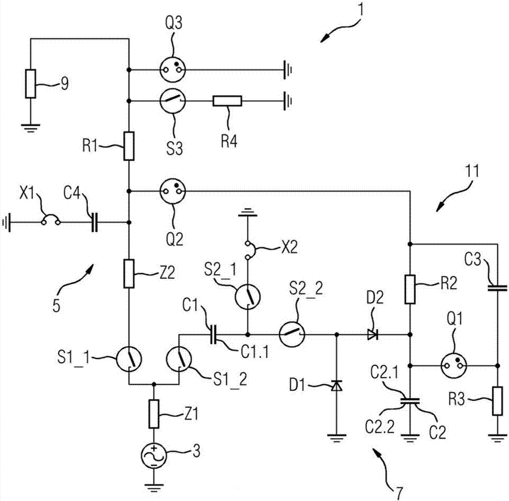
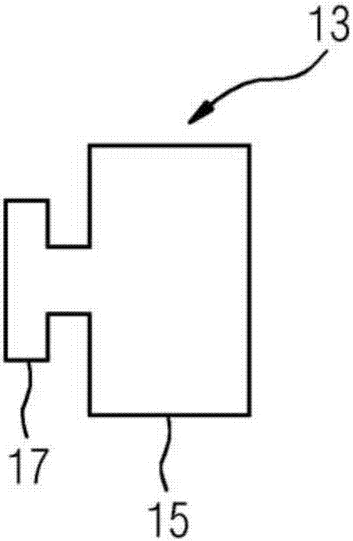
[0038] figure 1 shown in figure 1 A circuit diagram of a circuit arrangement 1 of a high-voltage test device 13 for a high-voltage test, not shown in FIG. 2 , wherein, as described below, the various components of the circuit arrangement 1 shown are optional.

[0039] The circuit arrangement 1 comprises an AC voltage source 3, a first circuit branch 5 electrically connectable to the AC voltage source 3 via a first switch S1_1 and a second circuit branch 7 electrically connectable to the AC voltage source 3 via a second switch S1_2 . The switches S1_1 and S1_2 can also be realized together as a transfer switch.

[0040] The AC voltage source 3 preferably includes a variable transformer for generating relatively high AC voltages, for example with an effective value of up to 750 kV.

[0041] An alternating voltage can be applied to the test piece 9 by means of the first circuit branch 5 .

[0042] For performing alternating current partial discharge measurements, the first ci...


PUM


Abstract

The invention relates to a circuit assembly (1) for high-voltage tests. The circuit assembly (1) comprises an alternating voltage source (3) and at least two circuit branches (5, 7), each of which can be electrically connected to the alternating voltage source (3). An alternating voltage can be applied to a test object (9) by means of a first circuit branch (5), and a direct voltage can be applied to the test object (9) by means of a second circuit branch (7), which rectifies an alternating voltage.

Description

technical field [0001] The invention relates to a circuit device and high voltage testing equipment for high voltage testing. Background technique [0002] Complete high voltage testing of high voltage products requires in particular AC and / or DC voltage testing as well as impulse voltage testing. As a routine and / or type test for AC voltage products, the AC voltage test is most commonly used. However, more and more DC voltage tests are also required as routine and / or type tests for DC voltage products in the growing market. [0003] The testing of both product categories, ie DC voltage products and AC voltage products additionally requires an impulse voltage test. Two types of impulse voltage tests are required here: so-called switching impulse and lightning impulse tests. From a technical point of view, a switching pulse test is usually sufficient as a special test or type test and is usually practiced as such. The number of switching bump tests to be performed is ther...

Claims


Application Information

Patent Timeline
Patent Type & Authority Applications(China)
IPC IPC(8): G01R31/14H02M1/00
CPCG01R31/14G01R31/3272H02M1/10H02M7/06G01R31/62G01R31/40G01R1/04
Inventor M.博克
Owner SIEMENS ENERGY GLOBAL GMBH CO & KG
Why Eureka
Try Eureka