
Method and device for processing signals

A technology for processing signals and signals, applied in the field of communication, can solve problems such as large logic resource requirements, high hardware requirements, complex LMS algorithm architecture, etc., to achieve low power consumption and reduce system overhead

Active Publication Date: 2020-01-03
HUAWEI TECH CO LTD
View PDF7 Cites 0 Cited by
  • Summary
  • Abstract
  • Description
  • Claims
  • Application Information

AI Technical Summary

Problems solved by technology

The LMS algorithm architecture is complex, requires large logic resources, and requires high hardware requirements

Method used


Image

  • Method and device for processing signals
  • Method and device for processing signals
  • Method and device for processing signals

Examples


Embodiment Construction

[0044] The following will clearly and completely describe the technical solutions in the embodiments of the present invention with reference to the accompanying drawings in the embodiments of the present invention. Obviously, the described embodiments are part of the embodiments of the present invention, not all of them. Based on the embodiments of the present invention, all other embodiments obtained by persons of ordinary skill in the art without making creative efforts shall fall within the protection scope of the present invention.

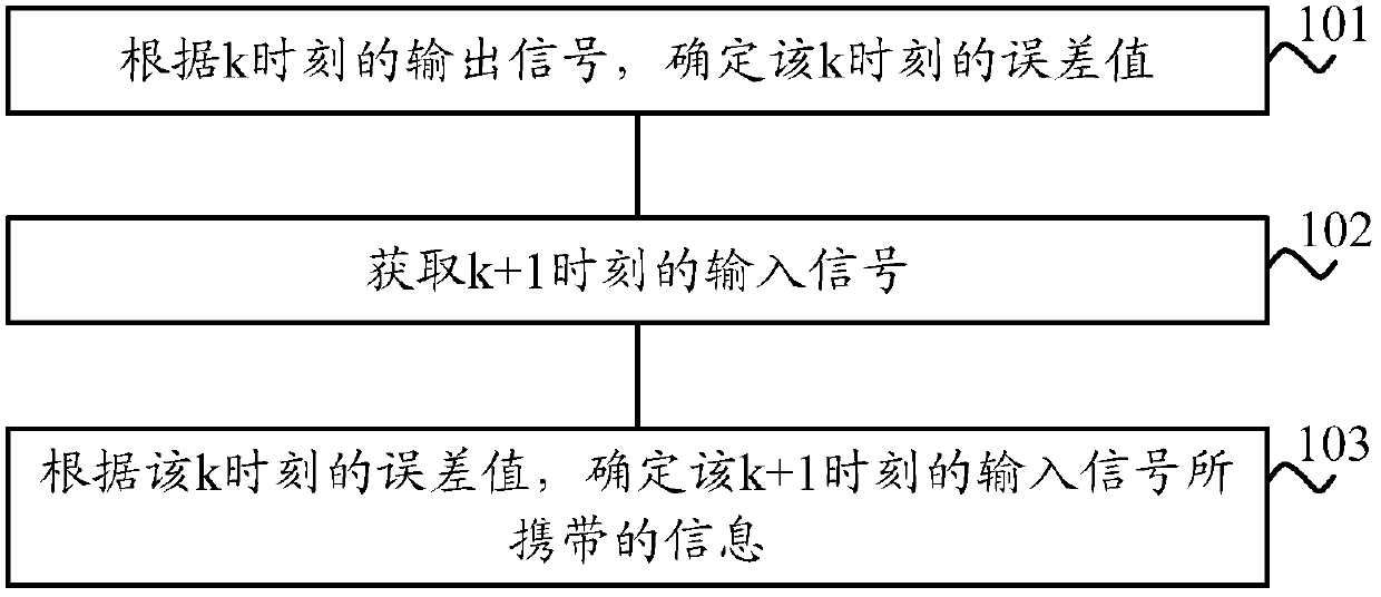
[0045] figure 1 is a schematic flowchart of a method for processing a signal according to an embodiment of the present invention.

[0046] 101. Determine an error value at time k according to the output signal at time k.

[0047] 102. Acquire an input signal at time k+1, where the input signal at time k+1 is a signal obtained after signal resampling, optical fiber link dispersion estimation, and dispersion compensation processing.

[0048] 1...


PUM


Abstract

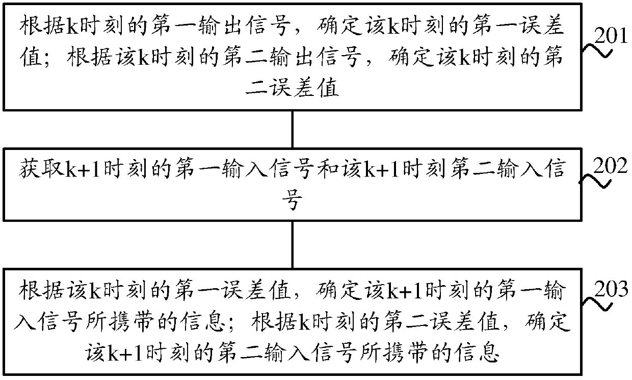
Provided in embodiments of the present invention are a method and device for processing a signal. The method comprises: according to an output signal at time k, determining an error value for the time k; obtaining an input signal at time k+1, wherein the input signal at the time k+1 is a signal obtained from signal re-sampling, optical fiber link dispersion assessment and dispersion compensation processing; according to the error value at the time k, determining information carried by the input signal at the time k+1. The above solution does not require assistance of a training sequence, and has a lower complexity.

Description

technical field [0001] Embodiments of the present invention relate to the field of communication technologies, and more specifically, to a method and device for processing signals. Background technique [0002] The coverage area of ​​the metro transmission system is usually 80 km to 600 km. In order to increase the signal transmission distance to hundreds of kilometers, the metro transmission system using intensity modulation and direct detection usually uses multi-carrier and reduces the symbol rate of each carrier to improve the tolerance of dispersion, or in the link Place the optical dispersion compensating element in it. In addition, the metro transmission system may also include transmission systems of different rates (for example, a 10G transmission system and a 100G transmission system may exist in the metro transmission system). The mixed transmission of signals in transmission systems with different rates may bring nonlinear effects. In order to solve the above ...

Claims


Application Information

Patent Timeline
IPC IPC(8): H04L27/148
CPCH04L27/148
Inventor 卢彦兆
Owner HUAWEI TECH CO LTD
Learn More