
Negative pressure test tube amniocentesis device

A technology of amniocentesis and test tubes, which is applied in the field of medical products, can solve the problems of high labor intensity, manpower occupation, and heavy workload, and achieve the effects of improving the extraction rate, good use effect, and strong practicability

Pending Publication Date: 2017-09-29
PEKING UNIV SHENZHEN HOSPITAL
View PDF15 Cites 0 Cited by
  • Summary
  • Abstract
  • Description
  • Claims
  • Application Information

AI Technical Summary

Problems solved by technology

[0004] In hospitals, as few as dozens of pregnant women and as many as hundreds of pregnant women need to undergo amniocentesis every day, so manual extraction makes the workload and labor intensity high, making it impossible to increase the extraction rate and improve the work efficiency of medical staff. When the personnel extract manually, at least two medical personnel need to cooperate to operate, that is, one person holds the medical ultrasonic probe in one hand and the other hand holds the PTC puncture needle for puncture, and the other person holds the syringe for suction, which will occupy manpower and increase labor costs , and when the two medical staff cooperate with each other, if the cooperation is not good, it will take a long time for amniocentesis, which will also reduce the work efficiency of the medical staff. Tiredness and inaccurate puncture make it easy to penetrate the PTC puncture needle into the anterior pelvis of pregnant women and cause fetal pelvic bleeding, resulting in puncture failure

Method used


Image

  • Negative pressure test tube amniocentesis device
  • Negative pressure test tube amniocentesis device
  • Negative pressure test tube amniocentesis device

Examples


Embodiment Construction

[0046] The technical solution of the present invention will be described in detail below in conjunction with the accompanying drawings and specific embodiments, so as to understand the essence of the present invention more clearly and intuitively.

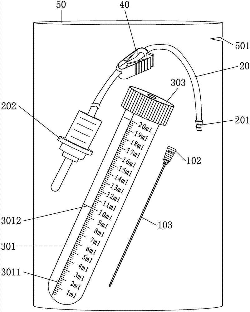
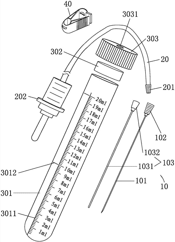
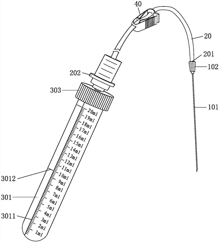
[0047] combine figure 1 , figure 2 , image 3 and Figure 4 shown;

[0048] A negative pressure test tube amniocentesis device provided by the present invention includes a PTC puncture needle 10, an amniotic fluid suction tube 20 and a negative pressure test tube 30;

[0049] Wherein, the liquid inlet end of the amniotic fluid straw 20 is detachably connected to the liquid outlet end of the PTC puncture needle 10, and the liquid outlet end of the amniotic fluid straw 20 is detachably connected to the liquid inlet end of the negative pressure test tube 30. connect.

[0050] Based on the above, it can be clarified that the negative pressure test tube 30 amniocentesis device provided by the present invention, in actual implementat...


PUM

PropertyMeasurementUnit
Capacityaaaaaaaaaa

Abstract

The invention discloses a negative pressure test tube amniocentesis device. The negative pressure test tube amniocentesis device comprises a PTC puncture needle, an amniotic fluid sucker and a negative pressure test tube. The liquid inlet end of the amniotic fluid sucker is detachably connected with the liquid outlet end of the PTC puncture needle, and the liquid outlet end of the amniotic fluid sucker is detachably connected with the liquid inlet end of the negative pressure test tube. When performing amniocentesis on a pregnant woman to extract amniotic fluid, medical staff connect the liquid outlet end of the PTC puncture needle with the liquid inlet end of the amniotic fluid sucker, insert the end of the PTC puncture needle into the amniotic cavity of the pregnant woman and then connect the liquid outlet end of the amniotic fluid sucker to the liquid inlet end of the negative pressure test tube, then the amniotic fluid in the amniotic cavity of the pregnant woman can be automatically sucked into the negative pressure test tube through the PTC puncture needle and the amniotic fluid sucker to be stored through the negative pressure formed in the negative pressure test tube, the trouble of manual suction with an injector is avoided, the working load and the labor intensity of medical staff can be relieved, the extraction speed can be greatly increased, and thus the negative pressure test tube amniocentesis device is high in practicability and good in use effect.

Description

technical field [0001] The invention relates to the technical field of medical products, in particular to a negative pressure test tube amniocentesis device. Background technique [0002] Amniocentesis, as the name suggests, is a method of prenatal diagnosis, generally suitable for prenatal diagnosis in the second trimester. Amniotic fluid exists in the amniotic cavity; the fertilized egg forms the amniotic cavity on the seventh day of fertilization and begins to produce amniotic fluid. The amniotic fluid volume is 50 ml at 12 weeks of pregnancy, 400 ml at 20 weeks, and 1000-1500 ml at 36 to 38 weeks. The amount of amniotic fluid decreased slightly near the expected date of delivery. [0003] In existing major hospitals, when pregnant women are given prenatal diagnosis to check whether the fetus has congenital defects, such as whether there is a cleft lip or congenital diseases, it is usually necessary to use a syringe to connect to a PTC puncture needle. Under the develop...

Claims


Application Information

Patent Timeline
IPC IPC(8): A61B10/00
CPCA61B10/0048A61B2010/009
Inventor 石宇张蒂荣刘俐陈芸邓玉清薛利萍钟凯杨晓东王凤卿张艳萍钟世林叶盛孔凤贝
Owner PEKING UNIV SHENZHEN HOSPITAL
Learn More