
Lever type mechanical downward pushing device of mechanical press

A technology of mechanical press and ejector device, applied in forging/pressing/hammer device, forging/pressing/hammering machinery, push-out equipment, etc., can solve problems such as increasing production cost, reducing production efficiency, and small ejecting force

Active Publication Date: 2017-09-29
RONGCHENG HUADONG METAL FORMING MACHINERY
View PDF7 Cites 19 Cited by
  • Summary
  • Abstract
  • Description
  • Claims
  • Application Information

AI Technical Summary

Problems solved by technology

The above-mentioned mechanism converts force too many times (up to 3 times), the energy loss is large, the structure is more complicated, and the manufacturing cost is high; and after the cam-type mechanical lowering device and the ejection are completed, the impact is large when resetting, and the cam, resetting The spring wears quickly, the upper swing rod is easy to wear, break, and the cam is stuck, and the maintenance cost is high, which increases the production cost and reduces the production efficiency, which does not meet the current manufacturing enterprises' requirements for green and energy-saving production.
The most important thing is that the forging extrusion or tensile force requirements of the lower ejector exceeding 30% of the nominal force cannot be realized by the cam-type mechanical lower ejector device.
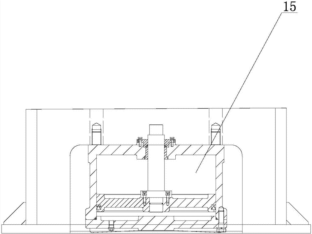
[0004] like image 3 As shown in the figure, the pneumatic lower ejecting device hangs the cylinder under the base, the piston rod is directly connected with the ejector rod, and directly ejects the material through the movement of the cylinder. The mechanism is simple in structure and reliable in operation, but the ejection force is relatively small It is used to eject the parts from the mold after the parts are stamped, which cannot meet the requirements of forging and extrusion work
At present, it is only used on a small number of small mechanical presses that do not require high material ejection force.

Method used


Image

  • Lever type mechanical downward pushing device of mechanical press
  • Lever type mechanical downward pushing device of mechanical press
  • Lever type mechanical downward pushing device of mechanical press

Examples


Embodiment Construction

[0038] In order to clearly illustrate the technical features of this solution, the present invention will be described in detail below through specific implementation modes and in conjunction with the accompanying drawings.

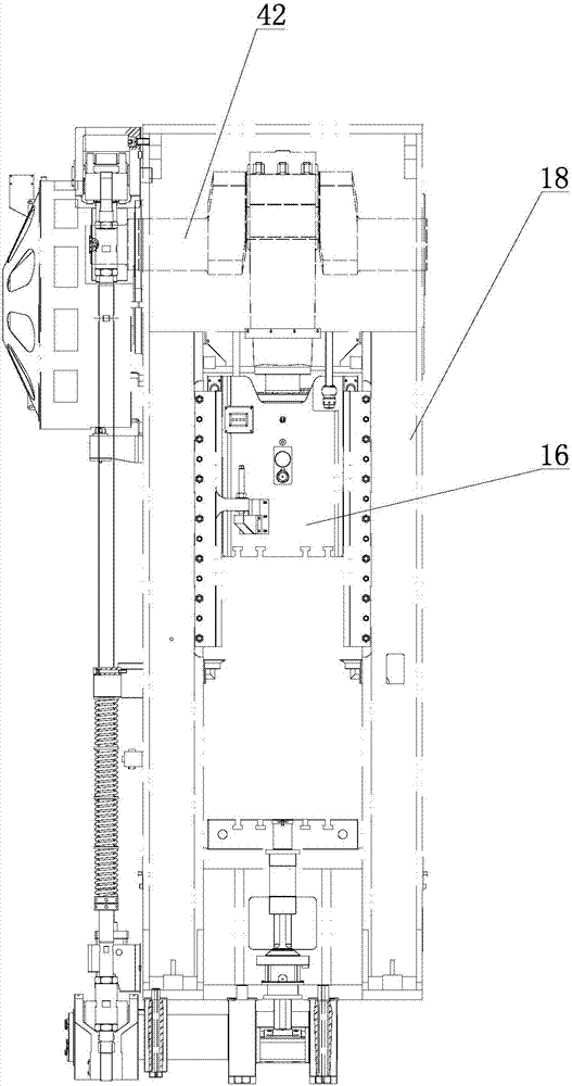
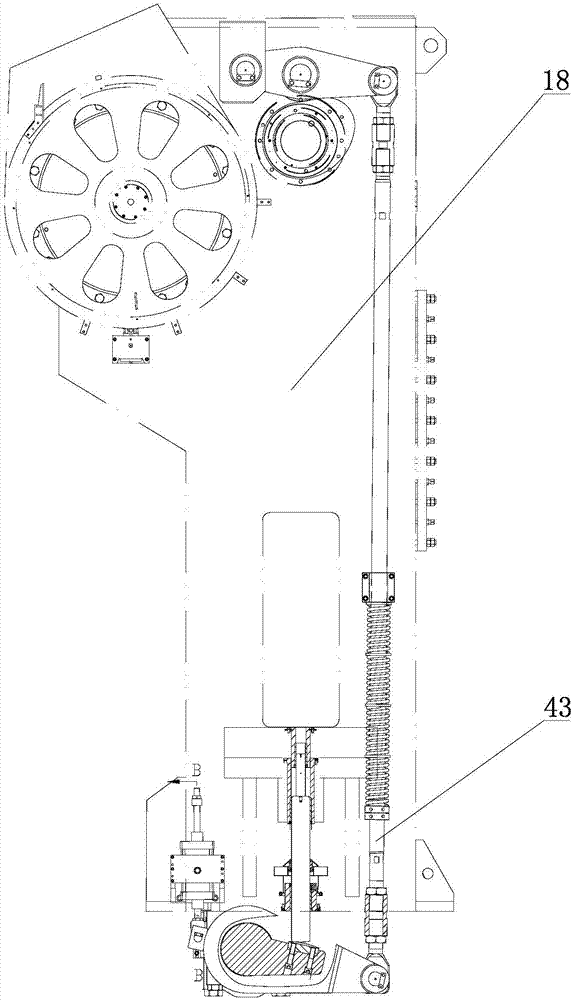
[0039] Such as Figure 4-9As shown, a mechanical press lever type mechanical lower material jacking device includes a slide block 16 installed on the fuselage 18, the two sides of the slide block 16 are respectively provided with brackets 4 connected with the vertical upper pull rod 3, and the upper pull rod 3 passes through The adjustment nut 6 is connected with the pull-down rod 7, the lower end of the pull-down rod 7 is fixedly connected with the pull rod joint 12, the pull rod joint 12 is connected with the outer end of the horizontally arranged lever 14 by turning and sliding, the middle part of the lever 14 is connected with the fulcrum seat 10 arranged on the fuselage 18 Rotationally connected, the other end of the lever 14 is rollingly connected w...


PUM


Abstract

A lever type mechanical downward pushing device of a mechanical press comprises a sliding block mounted on a machine body. Supports are mounted on the two sides of the sliding block correspondingly to be connected with vertical upper pull rods. The upper pull rods are connected with lower pull rods through adjusting nuts. The lower ends of the lower pull rods are fixedly connected with pull rod connectors. The pull rod connectors are rotatably and slidably connected with the outer ends of horizontally-arranged levers. The middles of the levers are rotatably connected with fulcrum seats arranged on the machine body. The other ends of the levers are in rolling connection with the lower bottom faces of a pushing seat. The upper end of the pushing seat is vertically and movably arranged in the machine body. A through hole is formed in the center of the pushing seat. An air cylinder is arranged at the bottom of the pushing seat. A piston rod of the air cylinder is mounted in the through hole. The upper end of the pushing seat is in matched connection with the lower end of an upper pushing rod. The upper end of the upper pushing rod is in matched connection with a worktable. The lever type mechanical downward pushing device has the advantages that synchronization is good, symmetrical balance is achieved, ejecting force is large, structure is simple, compactness is achieved, mechanical efficiency is high, manufacturing cost is low, maintenance is easy, environmental friendliness and energy saving are achieved.

Description

Technical field: [0001] The invention relates to the technical field of mechanical presses, in particular to a lever type mechanical bottom jacking device of a mechanical press. Background technique: [0002] The lower jacking device is one of the main components of the mechanical press. The lower jacking devices used by the existing mechanical presses are mainly divided into two types according to the driving mode, one is the cam type lower jacking devices used by most of them, and the other is a small number of mechanical presses, especially small mechanical presses. The above two kinds of lower ejecting devices are mainly used for mechanical press forging and ejecting parts after forging. [0003] But now, with the rapid development of the manufacturing industry and fierce market competition, manufacturing companies have put forward higher requirements for the equipment they purchase-reducing energy consumption, improving mechanical efficiency, and green production. The...

Claims


Application Information

Patent Timeline
IPC IPC(8): B21J13/14B21D45/02
CPCB21D45/02B21J13/14
Inventor 邱玉良郝玉琴徐海磊赵锦刚王鹏波彭鑫亮
Owner RONGCHENG HUADONG METAL FORMING MACHINERY
Learn More