Machining method for compressor disc

A compressor disk and processing method technology, applied in the processing field, can solve the problems of poor processing stability, large deformation, high scrap rate, etc., and achieve the effects of avoiding stress deformation, solving large deformation, and minimizing radial force

Inactive Publication Date: 2017-09-29
HARBIN DONGAN ENGINE GRP
View PDF7 Cites 5 Cited by
  • Summary
  • Abstract
  • Description
  • Claims
  • Application Information

AI Technical Summary

Problems solved by technology

[0003] The purpose of the present invention is to provide a processing method for compressor discs, which solves the problems of large deformation, poor processing stability and high scrap rate in the existing processing process

Method used


Image

  • Machining method for compressor disc
  • Machining method for compressor disc

Examples


Embodiment Construction

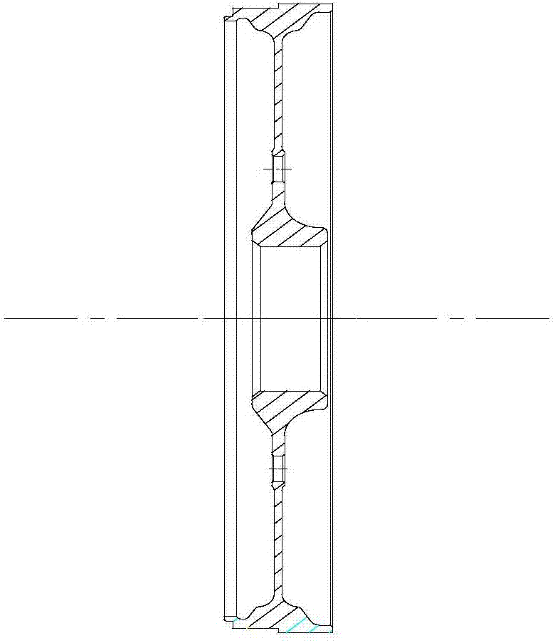
[0014] As shown in the figure, the described compressor disk processing method includes the following steps:

[0015] (1) After finishing the rough machining of parts, carry out semi-finishing on the thin-walled parts such as the seam on both sides of the compressor disc, the end face and the profile, and only keep a machining allowance of 0.5mm on one side according to the size of the drawing;

[0016] (2) Stress relief after semi-finishing: the stress relief equipment adopts a vacuum furnace, the parts are put into the furnace horizontally, the distance is ≥30mm, the holding temperature is 500±10°C, and the holding time is 2.5~3h. Baked at less than 100°C;

[0017] (3) Grinding positioning surface: use ordinary plane grinding positioning surface, that is, grind the reference end surface of the finish car, and finally make the flatness of the surface less than 0.005mm;

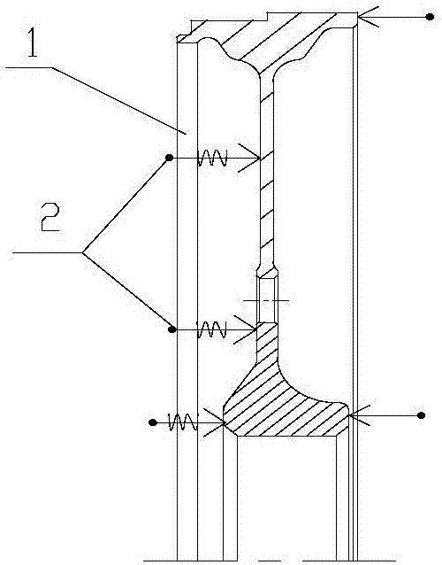
[0018] (4) Finishing: install the parts in the self-made fixture 1 on the CNC lathe equipment, and proces...


PUM


Abstract

The invention relates to a machining method for a compressor disc. By adding the stress relieving process after rough machining and before finish machining, the cutting depth and the blade angle of finish machining are limited, a self-made clamp is adopted to conduct axial supporting and compressing, and thus a part is machined. By setting the process steps, designing the clamping mode and selecting machining parameters, finally the deformation amount of the moulding surface and an stop opening of the compressor disc is reduced to be less than 0.005 mm, and the size tolerance and the geometrical tolerance both meet the drawing requirements.

Description

technical field [0001] The invention relates to a processing method, in particular to a processing method for a compressor disk, which is suitable for processing thin-walled and easily deformable compressor disks of aero-engines. Background technique [0002] With the gradual development of the world's aviation technology, higher requirements are put forward for the performance of the engine. The compressor disc is an important part of the turbofan engine compressor rotor (such as figure 1 shown), which plays a vital role in the performance of the engine. The compressor disk is a typical thin-walled and easily deformed part, and the thinnest part of the compressor plate is notched and shaped. The existing processing method is to perform simple rough machining on the quenched and tempered blank, and then directly finish machining to the final size. The parts processed by this process method retain a large amount of residual stress inside. Due to the thin wall thickness of ...

Claims


Application Information

Patent Timeline
Patent Type & Authority Applications(China)
IPC IPC(8): B23P15/00
CPCB23P15/00B23P2700/01
Inventor 程明吕文生顾志勇曾桃飞宋秀峰刘昌伟
Owner HARBIN DONGAN ENGINE GRP
Why Eureka
Try Eureka