Aspherical mirror embryo eliminating edge effect

A technology of aspheric mirror and edge effect, which is applied in the direction of mirrors, optical surface grinders, grinders, etc., and can solve problems such as stress and deformation

Active Publication Date: 2018-05-18
SUZHOU BANGTIKE INTELLIGENT TECH CO LTD
View PDF5 Cites 2 Cited by
  • Summary
  • Abstract
  • Description
  • Claims
  • Application Information

AI Technical Summary

Problems solved by technology

[0004] The purpose of the invention is to overcome the deficiencies in t

Method used


Image

  • Aspherical mirror embryo eliminating edge effect
  • Aspherical mirror embryo eliminating edge effect
  • Aspherical mirror embryo eliminating edge effect

Examples


Embodiment 1

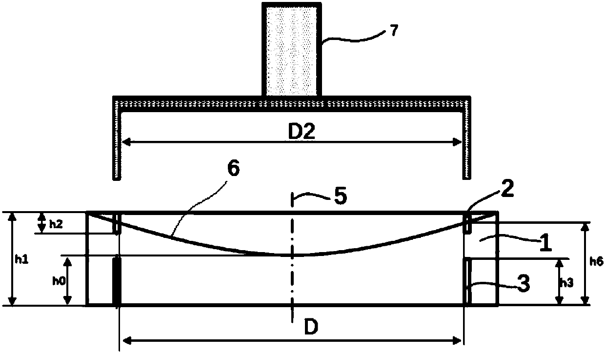
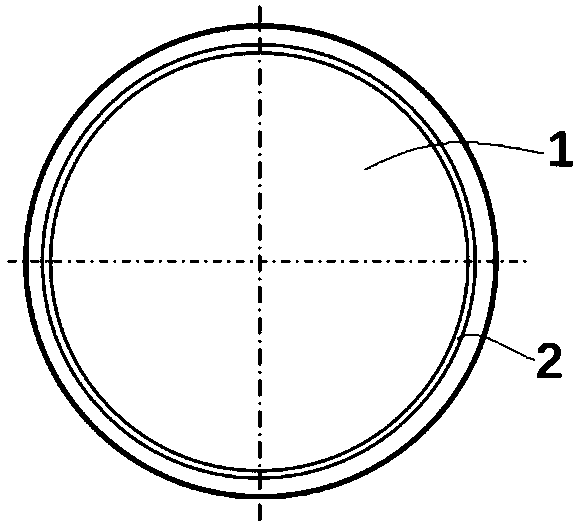
[0025] Embodiment one: as attached Figure 6 or Figure 7 An aspheric mirror blank with edge effect elimination shown: the aspherical mirror blank is composed of a cylindrical mirror blank 1, which includes a first end face 8, a second end face 9, a cylindrical side wall 10, an aspheric surface The structure 6 is arranged on the first end surface 8, and it is characterized in that the aspheric surface structure is also provided with a first circular groove, wherein the rotation axis of the first circular groove coincides with the rotation axis of the aspheric surface, and the inner diameter of the first circular groove is larger than the diameter of the aspheric surface.

[0026] Attached below figure 1 , taking the rotating concave aspheric mirror with the machining diameter as D and the center thickness as h0 as an example to introduce the specific steps of using the above-mentioned cylindrical mirror blank to process the aspheric surface,

[0027] Step 1: Process a cylind...

Embodiment 2

[0032] Embodiment 2: On the basis of Embodiment 1, the depth of the first circular groove is greater than or equal to 2 mm, so that edge collapse of the aspheric surface can be effectively avoided during later trimming.

Embodiment 3

[0033] Embodiment three: as attached figure 1 - attached Figure 5 As shown, on the basis of the first embodiment, the second end face is also provided with a second end face round groove 3, wherein the rotation axis of the second end face round groove coincides with the aspheric rotation axis, and the second end face round groove and the first round groove The groove width and inner diameter are equal, and the depth of the circular groove 3 on the second end surface is h3, which satisfies h2+h3


PUM

PropertyMeasurementUnit
Depthaaaaaaaaaa

Abstract

The invention discloses an aspherical mirror embryo eliminating edge effect. The aspherical mirror embryo eliminating edge effect is characterized in that the aspherical mirror embryo is made of a cylindrical mirror embryo being greater than the aspherical caliber; the cylindrical mirror embryo includes a first end surface, a second end surface, and a cylindrical surface sidewall; an aspherical structure is located at the first end surface of the cylindrical mirror embryo; a first circular groove is also formed in the aspherical structure; the revolving axis of the first circular groove and the revolving axis of the aspherical surface are coincided; the internal diameter of the first circular groove is greater than the caliber of the aspherical surface; and when the mirror is used to process the aspherical surface, the range in which the edge effect occurs is controlled in the annular area outside the first circular groove on the aspherical surface, and the annular area outside the caliber of the aspherical surface is removed and then the residual part is a reflector having no edge effect. The technical scheme of the aspherical mirror embryo eliminating edge effect effectively solves the edge effect problem and the stress deformation problem, and is not easy to generate breakage edge and breakage opening at the edge of the aspherical surface.

Description

technical field [0001] The invention belongs to the field of optical processing, and in particular relates to a mirror blank used for processing aspheric surfaces. Background technique [0002] With the further development of computer numerical control single-point diamond technology, ultra-precision grinding technology, computer-controlled optical surface forming technology and other aspheric processing technologies, the current manufacturing technology of aspheric optical elements has developed from traditional manual modification of spherical surfaces to computer control. Deterministic process. However, neither the traditional classical polishing technology nor the computer-controlled small grinding head polishing technology has a fast and effective method to solve the problem of the edge effect of aspheric mirrors. The edge effect is caused by the fact that the removal rate of the removal function is the largest at the center of the polishing, and the removal rate is th...

Claims


Application Information

Patent Timeline
IPC IPC(8): G02B5/10B24B13/00
CPCB24B13/00G02B5/10
Inventor 陈曦郭培基王伟
Owner SUZHOU BANGTIKE INTELLIGENT TECH CO LTD
Why Eureka
Try Eureka