Robot self-calibration method based on vision-assisted positioning

An auxiliary positioning and robot technology, applied in the direction of manipulators, program-controlled manipulators, manufacturing tools, etc., can solve the problems of low absolute positioning accuracy, complicated measurement process, high cost, etc., to avoid manual teaching measurement, high measurement efficiency and low cost low effect

Inactive Publication Date: 2017-09-29
JIANGNAN UNIV
View PDF4 Cites 31 Cited by
  • Summary
  • Abstract
  • Description
  • Claims
  • Application Information

AI Technical Summary

Problems solved by technology

[0002] 1. Robot positioning accuracy is an important index to measure its working performance. At present, due to factors such as manufacturing and installation, most of the robots produced by domestic and foreign manufacturers have low absolute positioning accuracy and cannot meet the needs of high-precision machining and offline programming. , analyzing various factors that cause robot positioning errors, and maximizing the absolute positioning accuracy of robots has become the core content of robotics research
[0003] 2. At present, the commonly used robot calibration methods at home and abroad usually require the help of external advanced measurement equipment, which is costly and complicated in the measurement process, requiring professionals to operate; at the same time, due to the conversion between the measurement coordinate system and the robot base coordinate system In the process, it is easy to introduce the error of the coordinate system ring, and the error is not the same type of error as the error of the robot connecting rod parameter. It needs to be dealt with separately, and the process is more complicated.
[0004] 3. In order to reduce costs and other factors, many researchers have proposed a closed-loop calibration method, that is, to attach a constraint to the end of the robot, and more surface constraints (plane or spherical surfaces) are used. However, when performing contact measurements on these surfaces, Most of them adopt the method of manual teaching, the measurement process is time-consuming and laborious, and the efficiency is very low

Method used


Image

  • Robot self-calibration method based on vision-assisted positioning
  • Robot self-calibration method based on vision-assisted positioning
  • Robot self-calibration method based on vision-assisted positioning

Examples


Embodiment Construction

[0043] The preferred embodiments of the present invention will be described below in conjunction with the accompanying drawings. It should be understood that the preferred embodiments described here are only used to illustrate and explain the present invention, and are not intended to limit the present invention.

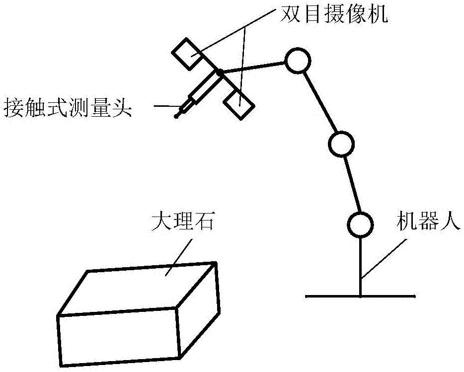
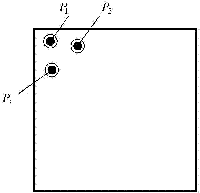
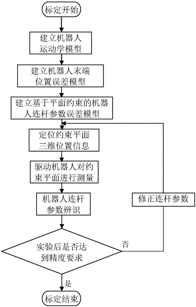
[0044] See attached Figure 1~3 , the robot self-calibration method based on vision-assisted positioning of the present invention comprises the following steps:

[0045] (1) Establish robot kinematics model

[0046] Establish a robot kinematics model combining D-H method and MD-H method, and describe the transformation process from coordinate system i-1 to coordinate system i as A i , A i =f(α i-1 ,a i-1 , d i ,θ i ,β i ), then the pose matrix of the robot end coordinate system n relative to the base coordinate system 0 T n for:

[0047] 0 T n =A 0 ·A 1 ·...·A n

[0048] (2) Establish the robot end position error model

[0049] According to the idea...


PUM


Abstract

The invention relates to a robot self-calibration method based on plane constraint and vision-assisted positioning. The robot self-calibration method based on plane constraint and vision-assisted positioning is used for obtaining real connection rod parameters of a robot. Firstly, a robot kinematic model combining a D-H method and a MD-H method is established; secondly, a robot terminal position error model is established; thirdly, a robot connection rod parameter error model based on plane constraint is established; fourthly, images, of a constraint plane, in a left camera and a right camera are obtained through binocular vision, target point information in each image is extracted, the three-dimensional position information of the constraint plane under a basic coordinate system of the robot is positioned through three-dimensional matching; the position information is input into a robot control system, and the robot is driven to measure the constraint plane; and finally the measured data are substitute into the plane constraint error model, the real geometric connection rod parameters of the robot are recognized, and after correction, measurement of the constraint plane and recognition are repeatedly conducted until a precision requirement is met. The robot self-calibration method based on plane constraint and vision-assisted positioning has the advantages of being low in cost and high in precision and efficiency.

Description

technical field [0001] The invention relates to a robot self-calibration method, in particular to a robot self-calibration method based on plane constraints and vision-assisted positioning. Background technique [0002] 1. Robot positioning accuracy is an important index to measure its working performance. At present, due to factors such as manufacturing and installation, most of the robots produced by domestic and foreign manufacturers have low absolute positioning accuracy and cannot meet the needs of high-precision machining and offline programming. , analyze the various factors that cause the robot positioning error, and improve the absolute positioning accuracy of the robot as much as possible has become the core content of the robot technology research. [0003] 2. At present, the commonly used robot calibration methods at home and abroad usually require the help of external advanced measurement equipment, which is costly and complicated in the measurement process, req...

Claims


Application Information

Patent Timeline
Patent Type & Authority Applications(China)
IPC IPC(8): B25J9/16
CPCB25J9/1605B25J9/1697
Inventor 王晨学平雪良徐超蒋毅
Owner JIANGNAN UNIV
Why Eureka
Try Eureka