Detection method of braking response time of brake of elevator

An elevator brake and braking response technology, applied in the elevator field, can solve the problems of low precision and large detection error, and achieve the effect of improving accuracy, easy operation and reading

Active Publication Date: 2017-09-29
ZHEJIANG SCI-TECH UNIV
View PDF9 Cites 16 Cited by
  • Summary
  • Abstract
  • Description
  • Claims
  • Application Information

AI Technical Summary

Problems solved by technology

[0005] The purpose of the present invention is to provide a detection method for the braking response time of the elevator brake, aiming at the problems of relatively large detection error and low precision in the detection method of the existing elevator brake braking response time——the brake micro switch, More precise determination of the braking response time of elevator brakes

Method used


Image

  • Detection method of braking response time of brake of elevator
  • Detection method of braking response time of brake of elevator
  • Detection method of braking response time of brake of elevator

Examples


Embodiment Construction

[0023] In order to make the detection principle and features of the present invention easier to understand, the present invention will be further described below in conjunction with specific embodiments.

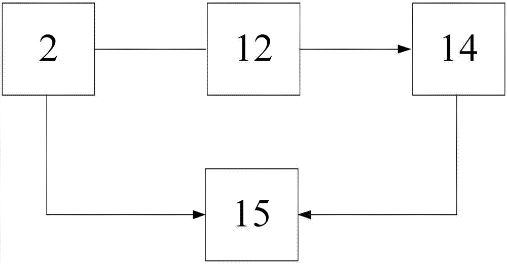
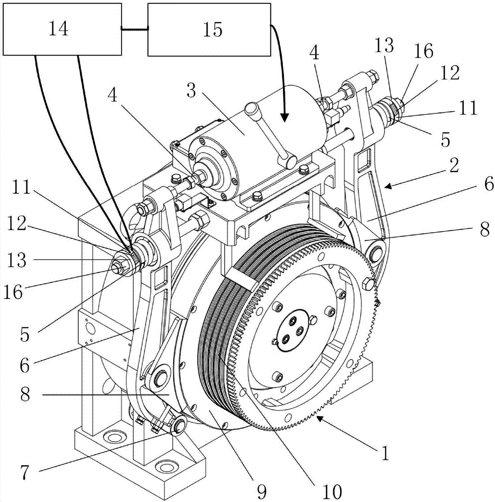
[0024] figure 1 It is the detection principle diagram of the elevator brake brake response time detection device in the present invention. The detection device is composed of a spring plate, a resistance strain gauge, a strain gauge and a dual-channel oscilloscope. The foil resistance strain gauge 13 is a high-precision dynamic strain gauge 14, and the detection object is the drum brake 2 installed on the permanent magnet synchronous gearless traction machine 1. The specific layout of the detection device is as follows: figure 2 As shown, the working principle of the drum brake 2 is: when the drum brake 2 is energized, the electromagnetic device 3 is energized to generate electromagnetic force, and the electromagnetic force drives the ejector rod 4 to move outward, and the ...


PUM


Abstract

The invention discloses a detection method of braking response time of a brake of an elevator. A method for detecting the braking response time of the brake of the elevator by the aid of a band brake micro-switch is relatively large in error and low in accuracy. According to the method, a spring plate with a resistance strain gauge attached is additionally mounted at one end of each brake spring, when the brake performs braking, the compression amounts of the brake springs are gradually reduced, when the brake completes braking, the compression amounts of the brake springs are minimum, the strain of the spring plates is minimum at the moment, the strain of the resistance strain gauges is also minimum, the change of the brake springs is detected through the resistance strain gauges and strain indicators, the braking response time of the brake is the time difference between an outage signal and the minimum strain moment of the resistance strain gauges, and the time difference can be directly read through a two-channel oscillography recording instrument. The method has the very high detection accuracy and universality and is also easy to operate.

Description

technical field [0001] The invention relates to the technical field of elevators, in particular to a method for detecting braking response time of elevator brakes. Background technique [0002] As the most important vertical means of transportation in high-rise buildings, the safety of elevators has always been the focus of attention, and the traction machine brake, as the most frequent device in traction elevators, is its most important safety component. In the event of a dangerous situation such as slipping down the ladder, falling to the bottom or rushing to the top, the brake is the first safety line of the elevator, and it is also the first lifeline of the passengers in the car. Therefore, the braking performance of the brake directly affects the safety performance of the entire elevator. [0003] The current elevator brakes are all electromechanical electromagnetic brakes, which are mainly composed of electromagnets, brake springs (compression springs) and brake shoes....

Claims


Application Information

Patent Timeline
Patent Type & Authority Applications(China)
IPC IPC(8): B66B5/00
CPCB66B5/0093
Inventor 许海刚陈文华冯国林金寅德方李进
Owner ZHEJIANG SCI-TECH UNIV
Why Eureka
Try Eureka