Supercharge Your Innovation With Domain-Expert AI Agents!

Power supply circuit and electromagnetic compatibility test system

A technology for power supply circuits and capacitors, which is applied in the parts of electrical measuring instruments, measuring electricity, measuring devices, etc., can solve the problems of increasing test costs, increasing operational difficulties, and high costs, reducing impact damage, reducing costs, and avoiding impact. damage effect

Active Publication Date: 2017-09-29
TIANJIN INST OF ADVANCED TECH
View PDF7 Cites 2 Cited by
  • Summary
  • Abstract
  • Description
  • Claims
  • Application Information

AI Technical Summary

Problems solved by technology

However, the greater the rated operating current of the artificial power network, the larger the volume and the higher the cost. Replacing the artificial power network with a larger rated current will increase the test cost and increase the difficulty of operation

Method used


Image

  • Power supply circuit and electromagnetic compatibility test system
  • Power supply circuit and electromagnetic compatibility test system

Examples


Embodiment 1

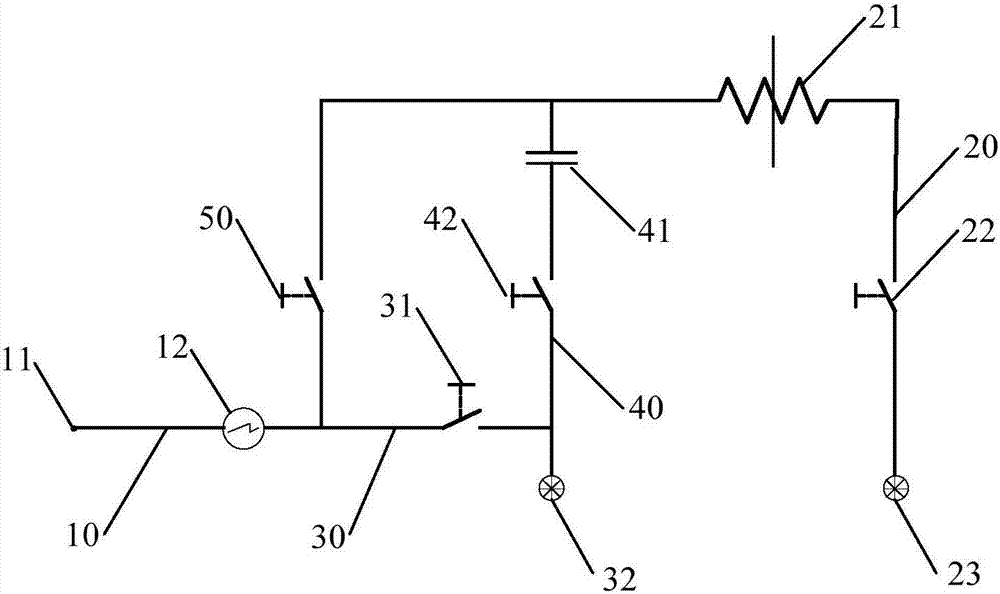
[0021] figure 1 It is a schematic structural diagram of a power supply circuit according to an embodiment of the present invention.

[0022] like figure 1 As shown, the power supply circuit of this embodiment includes a power supply branch 10 , a first power supply branch 20 and a second power supply branch 30 . Wherein, the first end of the power supply branch 10 is a power connection terminal 11 for connecting to the power supply network, and the first end of the first power supply branch 20 and the first end of the second power supply branch 30 are both connected to the power supply branch 10 The second end of the first power supply branch 20 is connected with an inductor 21 and a first switch device 22 ; the second power supply branch 30 is connected with a second switch device 31 .

[0023] In the power supply circuit of this embodiment, the power supply branch 10 can be connected to the power supply network through the power supply connection terminal 11, and the first...

Embodiment 2

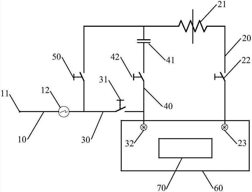
[0039] figure 2 It is a schematic structural diagram of an electromagnetic compatibility testing system according to an embodiment of the present invention. The electromagnetic compatibility testing system of this embodiment uses the power supply circuit of the first embodiment above to connect the artificial power supply network and the power supply network. The power supply circuit in this embodiment has the same structure as the power supply circuit in the first embodiment above, and will not be repeated here.

[0040] like figure 2 As shown, the electromagnetic compatibility testing system of this embodiment includes an artificial power supply network 60 and a power supply circuit. The first power supply branch 20 of the power supply circuit is connected to the output end of the artificial power supply network 60 , and the second power supply branch 30 is connected to the input end of the artificial power supply network 60 .

[0041] In the electromagnetic compatibili...


PUM


Abstract

The embodiment of the invention provides a power supply circuit and an electromagnetic compatibility test system. The power supply circuit comprises a power source branch, a first power supply branch and a second power supply branch. The first end of the power source branch is a power source connecting end used for being connected with a power supply network. The first end of the first power supply branch and the first end of the second power supply branch are connected with the second end of the power source branch. An electric inductor and a first switching device are connected on the first power supply branch. A second switching device is connected on the second power supply branch. With application of the technical scheme, the impact damage of high starting current of electrical equipment on the power supply network can be effectively reduced.

Description

technical field [0001] The invention relates to the technical field of power electronics, in particular to a power supply circuit and an electromagnetic compatibility testing system. Background technique [0002] Electro Magnetic Compatibility (EMC) is mostly used artificial power network (also known as power impedance stabilization network, Line Impedance Stabilization Network, LISN) to test the electromagnetic compatibility of the product under test. When the starting current of the product under test is too large, the difference between the starting current and the rated current of the artificial power network is large, which makes the inductance of the artificial power network large, resulting in a large starting current of the power supply network, causing damage to the power supply network. Some impact damage. [0003] When the starting current of the product under test is too large, the staff usually replaces the artificial power network with a larger rated operating...

Claims


Application Information

Patent Timeline
Patent Type & Authority Applications(China)
IPC IPC(8): G01R31/00G01R1/28
CPCG01R1/28G01R31/001
Inventor 吴建飞宿奉祥李雅菲王宏义郑黎明
Owner TIANJIN INST OF ADVANCED TECH
Features
  • R&D
  • Intellectual Property
  • Life Sciences
  • Materials
  • Tech Scout
  • Unparalleled Data Quality
  • Higher Quality Content
  • 60% Fewer Hallucinations
Learn More