A switch control circuit and control method

A switch control circuit, switch circuit technology, applied in electronic switches, circuit devices, control/regulation systems, etc., can solve the problems of output voltage drop, output voltage fluctuation, etc.

Active Publication Date: 2019-05-07
SILERGY SEMICON TECH (HANGZHOU) CO LTD
View PDF2 Cites 0 Cited by
  • Summary
  • Abstract
  • Description
  • Claims
  • Application Information

AI Technical Summary

Problems solved by technology

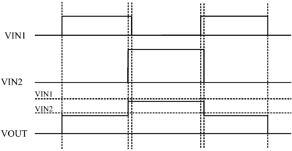
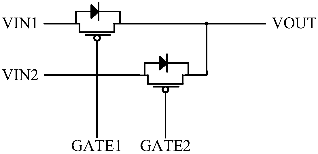
Compared with the first solution, this method can reduce the system loss due to the use of transistors, but the disadvantage is that in order to achieve the effect of unidirectional conduction (to prevent current backflow), the MOS transistor will be turned off before the ready voltage switching and after the complete switching, such as Figure 2B From t1 to t3, this will result in an output conversion drop voltage that is one diode drop lower than the output voltage during the switching process, such as Figure 2B In some applications (such as USB PD) the output conversion drop voltage of a diode drop voltage has far exceeded the allowable range
The disadvantage of this method is that there will be a drop in the output voltage during the switching process, and the value of this drop is related to the load, the size of the output capacitor, and the length of the dead time of the signal GATE1 and GATE2. When the output capacitor is small, it may be It leads to an unacceptable output voltage drop, and in some applications, there is an upper limit on the output capacitor, which causes greater fluctuations in the output voltage

Method used


Image

  • A switch control circuit and control method
  • A switch control circuit and control method
  • A switch control circuit and control method

Examples


Embodiment Construction

[0062] Several preferred embodiments of the present invention will be described in detail below with reference to the accompanying drawings, but the present invention is not limited to these embodiments. The present invention covers any alternatives, modifications, equivalent methods and schemes made on the spirit and scope of the present invention. In order to provide the public with a thorough understanding of the present invention, specific details are set forth in the following preferred embodiments of the present invention, but those skilled in the art can fully understand the present invention without the description of these details.

[0063] refer to Figure 4 Shown is a circuit block diagram of a switch control circuit according to the present invention, Figure 5 It is a specific circuit diagram of the switch control circuit. The switch control circuit is used to control a multi-way switch circuit, and the multi-way switch circuit includes a first switch circuit to ...


PUM


Abstract

The invention discloses a switch control circuit and a control method. When the external input voltage needs to be switched, the logic control circuit outputs a feedback control signal, and the feedback circuit participating in the switching process selects the reference voltage signal according to the feedback control signal. Need to switch the feedback loop of that channel, so as to control the switching action of the corresponding switch circuit to achieve the switching purpose of the input voltage. Through the above switching method, it can be ensured that the output voltage will not drop during the channel switching process, and the output value Stablize.

Description

technical field [0001] The invention relates to the field of switching power supplies, and more specifically, to a switching control circuit and a control method. Background technique [0002] In some applications with multiple input interfaces and single output ports, it is necessary to switch between different input power sources to output desired output voltage signals. Such as Figure 1A Shown is the first voltage switching method in the prior art, such as Figure 1A In the circuit diagram shown, taking two input interfaces as an example, the switching of multiple inputs is realized through the unidirectional conduction characteristic of the diode. Figure 1B shown as Figure 1A The waveform diagram shown. [0003] A diode is connected to the branch of each input port, the anode of the diode is connected to the input port, and the cathode is connected to the output port. When the voltage VIN1 of the first input terminal needs to be used, the voltage VIN1 is powered on,...

Claims


Application Information

Patent Timeline
Patent Type & Authority Patents(China)
IPC IPC(8): H02M3/158H02J9/06
CPCH02J9/061H02M3/1584H02J1/102H02M1/0003H02M3/158H02M3/157H03K17/6874H03K17/693H02J4/00
Inventor 蔡勇斌李俊杰
Owner SILERGY SEMICON TECH (HANGZHOU) CO LTD
Why Eureka
Try Eureka