Automatic joint debugging method for multi-light path imaging and device thereof

A multi-optical path, imaging technology, applied in medical science, ophthalmoscope, eye testing equipment, etc., can solve the problem of no multi-optical path joint adjustment mechanism, no multi-optical path adjustment automation, etc., to improve debugging repeatability and reduce operation. level requirements, the effect of reducing commissioning time

Pending Publication Date: 2017-10-03
ZD MEDICAL HANGZHOU CO LTD
View PDF4 Cites 8 Cited by
  • Summary
  • Abstract
  • Description
  • Claims
  • Application Information

AI Technical Summary

Problems solved by technology

[0002] Optical coherence tomography (OCT) technology is a new type of optical diagnostic imaging technology for non-invasive detection of biological tissues. Since light can easily reach eye tissues, it is very important to apply optical technology to ophthalmology. Good direction. At present, fundus imaging mainly uses the difference in reflectance between different tissue structures of the eye. Ophthalmic OCT images use false colors to represent different reflectivities. Currently, it is used in ophthalmic examination objectives and other multi-light path imaging systems, such as commercial OCT Goal, each optical path module is designed independently, and there is no multi-optical path joint adjustment mechanism. At present, each optical path can only be adjusted individually, and the adjustment process can only be completed manually, so professional staff are required to perform manual adjustments. Multiple Automation of optical path adjustment

Method used


Image

  • Automatic joint debugging method for multi-light path imaging and device thereof
  • Automatic joint debugging method for multi-light path imaging and device thereof
  • Automatic joint debugging method for multi-light path imaging and device thereof

Examples


Embodiment Construction

[0027] Below, the present invention will be further described in conjunction with the accompanying drawings and specific implementation methods. It should be noted that, under the premise of not conflicting, the various embodiments described below or the technical features can be combined arbitrarily to form new embodiments. .

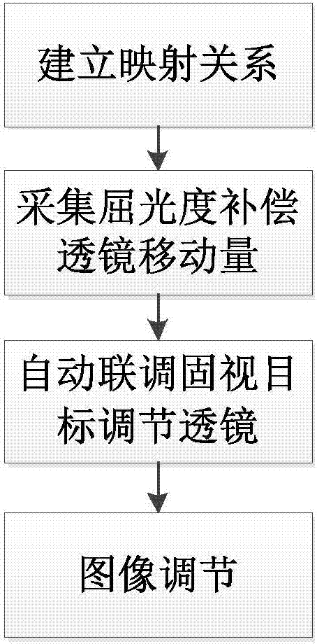
[0028] A multi-optical path imaging automatic joint adjustment method, such as figure 1 shown, including the following steps:

[0029] Establishing the mapping relationship, experimentally establishing the mapping relationship between the diopter compensation lens and the fixation target adjustment lens, experimentally establishing the mapping relationship between the diopter compensation lens and the fixation target adjustment lens, including experimentally establishing the mapping relationship between the movement amount of the diopter compensation lens and the movement amount of the fixation target adjustment lens, The diopter compensation lens inc...


PUM


Abstract

The invention provides an automatic joint debugging method for multi-light path imaging and a device thereof. The method includes the steps of building a mapping relation, collecting movement amount of dioptric offset lens, automatically conducting joint debugging on an adjustment lens of a vision fixing target, and adjusting an image. The invention also relates to the automatic joint debugging device for multi-light path imaging. The device includes a light-path imaging module and an adjustment module, wherein the light-path imaging module is provided with a light path unit, and the adjustment module is used for automatically adjusting the light path unit which is composed of an eye-ground coherence tomography unit, a vision fixing target imaging unit, a pupil imaging unit and an eye ground imaging unit; the vision fixing target imaging unit is provided with a third adjusting module, the eye-ground coherence tomography unit is provided with a second adjusting module, and the eye ground imaging module is provided with a third adjusting module. By installing the adjusting modules of different precision on a position in a need of adjustment according to the demands for precision adjustment, the automatic joint debugging method for multi-light path imaging is utilized to achieve automatic joint debugging of multi-light path imaging, so that the debug time is reduced, the debug repeatability is improved, and the demands of staff's operational levels are decreased.

Description

technical field [0001] The invention relates to a multi-optical path imaging device, in particular to a multi-optical path imaging automatic joint adjustment method and a device thereof. Background technique [0002] Optical coherence tomography (OCT) technology is a new type of optical diagnostic imaging technology for non-invasive detection of biological tissues. Since light can easily reach eye tissues, it is very important to apply optical technology to ophthalmology. Good direction. At present, fundus imaging mainly uses the difference in reflectance between different tissue structures of the eye. Ophthalmic OCT images use false colors to represent different reflectivities. Currently, it is used in ophthalmic examination objectives and other multi-light path imaging systems, such as commercial OCT Goal, each optical path module is designed independently, and there is no multi-optical path joint adjustment mechanism. At present, each optical path can only be adjusted ind...

Claims


Application Information

Patent Timeline
IPC IPC(8): A61B3/18A61B3/14A61B3/12
CPCA61B3/12A61B3/14A61B3/185
Inventor 胡献恩
Owner ZD MEDICAL HANGZHOU CO LTD
Why Eureka
Try Eureka