
Hydraulic door opening device

A hydraulic and water injection nozzle technology, applied in life-saving equipment, building rescue, etc., can solve the problems of unfavorable protection of indoor hostage personnel safety, large number of killing debris, reducing killing debris, etc., to achieve safe anti-terrorism rescue operations, wide range of blasting, and blasting low noise effect

Inactive Publication Date: 2017-10-03
江苏剑祥警用装备制造有限公司
View PDF10 Cites 0 Cited by
  • Summary
  • Abstract
  • Description
  • Claims
  • Application Information

AI Technical Summary

Problems solved by technology

In the early days, in order to ensure the effect of breaking the door, solid-state media were mostly used in door-breaking bullets. However, there are many problems with solid-state media. Safety of witnesses and others
For this reason, some door-breaking bullets use thin-shell materials and use directional high-pressure gas to break the door, but this only reduces the number of killing fragments, fails to solve the essential problem, and at the same time, the efficiency is very low

Method used


Image

  • Hydraulic door opening device
  • Hydraulic door opening device
  • Hydraulic door opening device

Examples


Embodiment 1

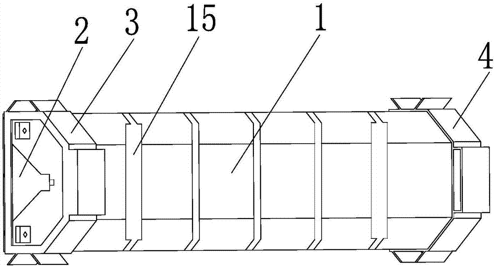
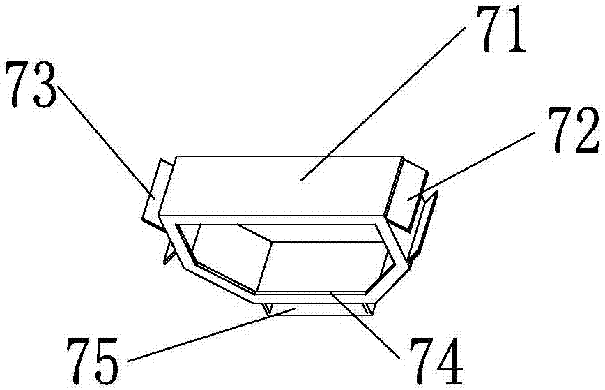
[0030] Such as Image 6 The shown hydraulic door breaking device connects two or more hydraulic door breaking devices side by side. The connection method is: connect the left connecting sleeve 3 on the right side of the inner eight-shaped plug 72 on one of the hydraulic door breaking devices to the corresponding The outer eight-shaped plug 73 on the left side of the left connecting sleeve 3 on the adjacent other hydraulic door breaking device is slidingly inserted into the combination; the outer eight-shaped plug 73 on the right side of the left connecting sleeve 3 on the right connecting sleeve 4 and The interlocking combination of the eight-shaped plug 72 on the left side of the left connecting collar 3 on another adjacent hydraulic door breaking device realizes the mutual locking between two or more hydraulic door breaking devices side by side.

Embodiment 2

[0032] Such as Figure 7 The shown hydraulic door breaking device connects two or more hydraulic door breaking devices in series. The connection method is: use a suitable piece of wood to pass through the left connecting collar 3 and the first hydraulic door breaking device in turn. The insert ring 75 of the right connecting ring 4 passes through the left connecting ring 3 and the insert ring 75 of the right connecting ring 4 on the first hydraulic door breaking device arranged axially, realizing two or more hydraulic power The series combination of door breaking device, the length of wood strip is about 5cm*0.8cm.

[0033] A hydraulic door breaking device of the present invention, the specific process of using this device:

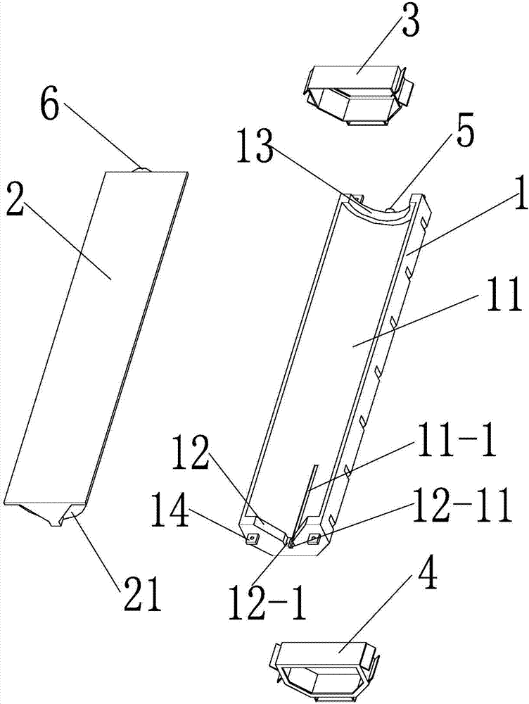
[0034] 1. Remove the left connecting collar 3 and the right connecting collar 4 from both sides, and separate the energy-concentrating bottle 1 from the broken bottle 2. The volume of the energy-forming bottle 1 is 1.1L, and the volume of the broken bottle 2 ...


PUM


Abstract

The invention relates to a hydraulic door opening device. The hydraulic door opening device comprises an energy gathering bottle, a destroying bottle, a left connection lantern ring, a right connection lantern ring, a first bottle cap and a second bottle cap. The energy gathering bottle and the destroying bottle are spliced and connected to form an integral structure. The left connection lantern ring is arranged on the left end portion of the energy gathering bottle, and the right connection lantern ring is arranged on the right end portion of the destroying bottle. The bottom face of the energy gathering bottle is provided with an inner arc-shaped concave face which is concaved inwards, the destroying bottle is provided with a projectile convex face which protrudes upwards, the projectile convex face is matched with the inner arc-shaped concave face, and a gap for distribution of a detonating cord segment exists between the projectile convex face and the inner arc-shaped concave face. After the hydraulic door opening device is used, no killing fragments are generated, the door opening efficiency can also be guaranteed, and anti-terrorist rescue activities are safer, quicker and more efficient; and by means of connection lantern rings, a plurality of hydraulic door opening devices can be assembled together, and the detonation range is wider.

Description

Technical field [0001] The invention relates to the field of door breaking devices, in particular to a hydraulic door breaking device. Background technique [0002] At present, the doorbreaker system tools used by firefighting, security, and the military are mainly used to quickly enter apartments, factories and public places in emergency and difficult situations. The so-called emergency situation, such as a fire, the discovery of criminals, etc.; the so-called difficult situation, refers to the entrance of these places generally have layers of anti-theft doors. [0003] In today's market, for blasting residents' security doors and wooden doors, door-breaking bullets are used. Door-breaking bullets are bombs that use explosive energy to blast the door. Explosion refers to a physical and chemical process in which energy undergoes rapid transformation in a limited volume. In the process of this change, the internal energy is quickly converted into mechanical compression energy, lig...

Claims


Application Information

Patent Timeline
Patent Type & Authority Applications(China)
IPC IPC(8): A62B3/00
CPCA62B3/005
Inventor 陈志君陈亦平
Owner 江苏剑祥警用装备制造有限公司
Learn More