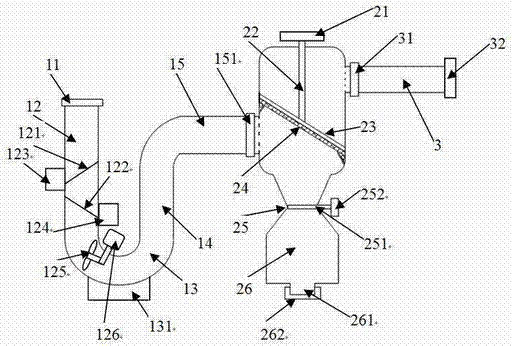
Filter pipeline for water conservancy project
A water conservancy project and pipeline technology, applied in the direction of filtration separation, filtration circuit, separation method, etc., can solve the problems of reducing water flow velocity, treatment, water flow pressure loss, etc., and achieve the effect of reducing replacement and cleaning and reducing costs
- Summary
- Abstract
- Description
- Claims
- Application Information
AI Technical Summary
Problems solved by technology
Method used
Image
Examples
Embodiment 1
[0032] A filter pipe for water conservancy engineering, comprising an inlet pipe part, a filter chamber and an outlet pipe part.
[0033] The inlet pipe part includes, in order, a pipe inlet fitting, a first vertical pipe, an elbow, a second vertical pipe, a cross pipe and a cross pipe joint.
[0034]The inlet joint is used as the water inlet of the entire filter pipeline, and a first sand screen and a second sand screen are installed in the first vertical pipe in sequence, and the first sand screen and the second sand screen are The filter screens are arranged inclined to each other and have an included angle with the first vertical pipe. The mesh diameter of the first sand and gravel filter screen is larger than the mesh diameter of the second sand and gravel filter screen. A first sand collection box is arranged at the junction of the terminal of the sand screen and the first vertical pipe, and a second collection box is arranged at the junction of the terminal of the secon...
Embodiment 2
[0051] A filter pipe for water conservancy engineering, comprising an inlet pipe part, a filter chamber and an outlet pipe part.
[0052] The inlet pipe part includes, in order, a pipe inlet fitting, a first vertical pipe, an elbow, a second vertical pipe, a cross pipe and a cross pipe joint.
[0053] The inlet joint is used as the water inlet of the entire filter pipeline, and a first sand screen and a second sand screen are installed in the first vertical pipe in sequence, and the first sand screen and the second sand screen are The filter screens are arranged inclined to each other and have an included angle with the first vertical pipe. The mesh diameter of the first sand and gravel filter screen is larger than the mesh diameter of the second sand and gravel filter screen. A first sand collection box is arranged at the junction of the terminal of the sand screen and the first vertical pipe, and a second collection box is arranged at the junction of the terminal of the seco...
Embodiment 3
[0071] A filter pipe for water conservancy engineering, comprising an inlet pipe part, a filter chamber and an outlet pipe part.
[0072] The inlet pipe part includes, in order, a pipe inlet fitting, a first vertical pipe, an elbow, a second vertical pipe, a cross pipe and a cross pipe joint.
[0073] The inlet joint is used as the water inlet of the entire filter pipeline, and a first sand screen and a second sand screen are installed in the first vertical pipe in sequence, and the first sand screen and the second sand screen are The filter screens are arranged inclined to each other and have an included angle with the first vertical pipe. The mesh diameter of the first sand and gravel filter screen is larger than the mesh diameter of the second sand and gravel filter screen. A first sand collection box is arranged at the junction of the terminal of the sand screen and the first vertical pipe, and a second collection box is arranged at the junction of the terminal of the seco...
PUM
| Property | Measurement | Unit |
|---|---|---|
| diameter | aaaaa | aaaaa |
| pore size | aaaaa | aaaaa |
| pore size | aaaaa | aaaaa |
Abstract
Description
Claims
Application Information
 - R&D
- Intellectual Property
- Life Sciences
- Materials
- Tech Scout
- Unparalleled Data Quality
- Higher Quality Content
- 60% Fewer Hallucinations
Browse by: Latest US Patents, China's latest patents, Technical Efficacy Thesaurus, Application Domain, Technology Topic, Popular Technical Reports.
© 2025 PatSnap. All rights reserved.Legal|Privacy policy|Modern Slavery Act Transparency Statement|Sitemap|About US| Contact US: help@patsnap.com

