A kind of methanation reactor and methanation process

A methanation reactor and reactor technology, applied in chemical instruments and methods, petroleum industry, chemical/physical processes, etc., can solve problems such as difficulty in eliminating thermal expansion and contraction stress, large pressure drop in reactor, difficulty in withstanding high pressure, etc. , to achieve the effect of improving the conversion rate of raw materials, increasing the degree of turbulence and prolonging the service life

Active Publication Date: 2019-10-15
SINOPEC ENG +1
View PDF8 Cites 0 Cited by
  • Summary
  • Abstract
  • Description
  • Claims
  • Application Information

AI Technical Summary

Problems solved by technology

The Chinese patent with the notification number CN202893334U discloses a microchannel reactor. The microchannel reactor adopts a titanium alloy plate structure, and each titanium alloy cooling cover plate is provided with a cooling chamber and a reaction chamber. The microchannel reactor can withstand High pressure and corrosion resistance, the disadvantage is that the reactant stays in the reaction chamber for a short time and the production efficiency is low
The Chinese patent with the notification number CN203540513U discloses a microchannel reactor used in the methanation process. The reactor fixes the microreaction channel on the support plate in the middle of the reactor, so it is difficult to eliminate the stress caused by thermal expansion and contraction
The Chinese patent with the notification number CN102151531A discloses a methanation reactor and a method for complete methanation of syngas. The microreactor is arranged in parallel with several reaction channels and heat transfer channels alternately, and the pressure drop of the reactor is relatively large. Difficult to withstand high pressure
The Chinese patents with the notification numbers CN204841617U and CN204816459U apply the methanation reactor to the coal-to-SNG methanation process, and the target product has high selectivity. The disadvantage is that the residence time of the feed gas in this type of reactor is relatively short. low raw material conversion rate

Method used


Image

  • A kind of methanation reactor and methanation process
  • A kind of methanation reactor and methanation process
  • A kind of methanation reactor and methanation process

Examples


Embodiment 1

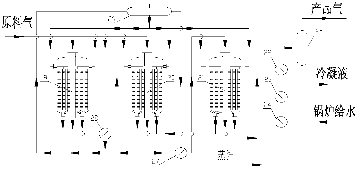
[0084] Such as image 3 As shown, the reaction device of this embodiment consists of 1# main methanation reactor 19, 2# main methanation reactor 20, 1# supplementary methanation reactor 21, 1# cooler 22, 2# cooler 23, boiler Feed water heater 24, product separator 25, steam drum 26, steam superheater 27 and 1# waste heat boiler 28 are connected. 1# main methanation reactor 19 and 2# main methanation reactor 20 are connected in series and parallel.

[0085] The operation steps are as follows:

[0086] 1. Put H 2 The / CO volume ratio is 3.0 (M=3.0), the synthesis gas with a pressure of 3.5MPa and a temperature of 280°C is divided into two streams, and the first stream enters the 1# main methanation reactor 19 for the 1# main methanation reaction. The temperature is 650°C, the pressure is 3.48MPa, and the volumetric space velocity is 9000h -1 , the reacted gas passes through the 1# waste heat boiler 28 to remove part of the heat, and enters the 2# main methanation reactor 20 ...

Embodiment 2

[0096] Such as Figure 6 As shown, the difference between the process used in this example and Example 1 is that 2# waste heat boiler 30 and 2# supplementary methanation are set between 1# supplementary methanation reactor and boiler feed water heater 24 in this example The reactor 29, the internal radial catalytic reaction zone of the main methanation reaction and supplementary methanation reactor are also different from the embodiment 1.

[0097] After passing through the 1# supplementary methanation reactor 21, the reaction materials are sent to the 2# supplementary methanation reactor 29 to continue the supplementary methanation reaction through the 2# waste heat boiler 30 to remove part of the heat, and the second product obtained is passed through the boiler feed water After the heater 24, the 2# cooler 23 and the 1# cooler 22 are lowered in temperature, the methanation product is separated after the product separator 25; the conversion rate of carbon monoxide is 99.99% ...

Embodiment 3

[0101] Such as Figure 9 As shown, the process adopted in this embodiment is the same as that in Embodiment 1. The difference is that the main methanation reactor used in this embodiment is different from the heat extraction equipment inside the supplementary methanation reactor, such as Figure 7 , Figure 8 shown.

[0102] In this embodiment, the conversion rate of carbon monoxide is 100%, the selectivity of methane is 97%, and superheated steam of 10.4MPa and 530°C is produced as a by-product.

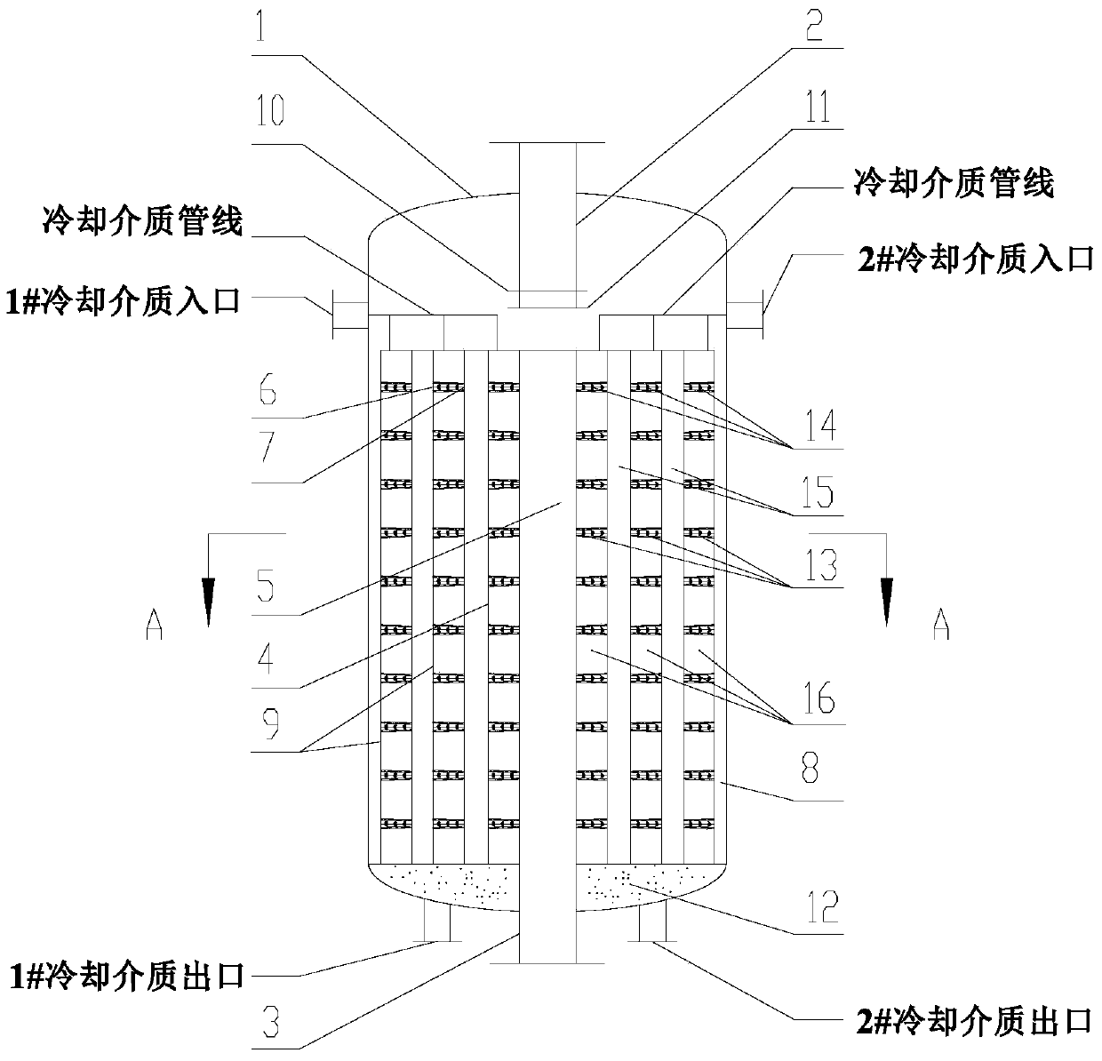
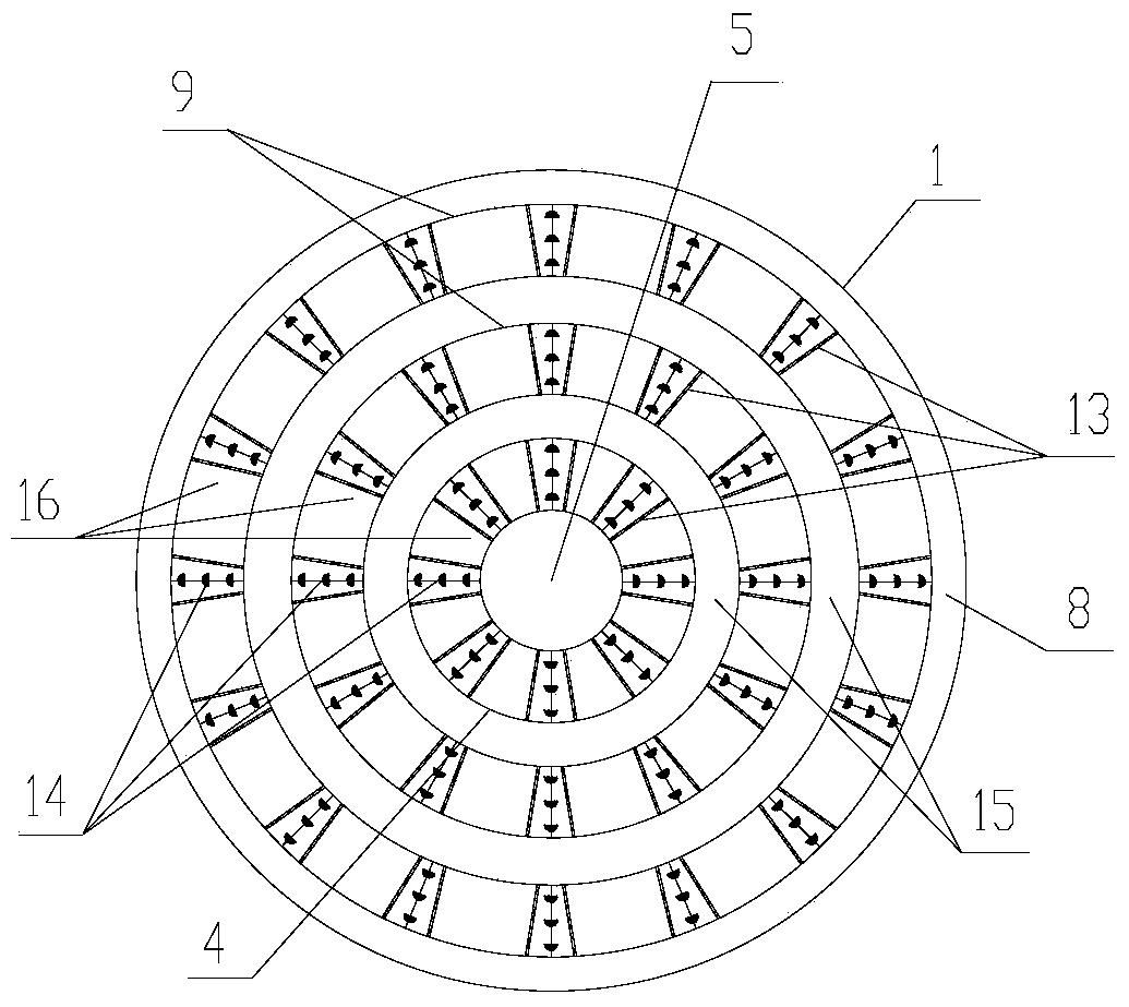
[0103] The difference between the methanation reactor used in this example and the methanation reactor used in Example 1 is that the heat extraction equipment in the methanation reactor used in this example is arranged in two collectors 15 , the cooling medium inlet and the medium outlet are in fluid communication through the cooling medium pipeline arranged in the manifold 15 and surrounding the central cylinder 4 and the sleeve 9 . The cooling medium enters the interior of the...


PUM

PropertyMeasurementUnit
heightaaaaaaaaaa
diameteraaaaaaaaaa

Abstract

The invention discloses a methanation reactor and a methanation process. The reactor comprises a cylindrical sealed pressure-bearing shell body (1), a gas inlet pipe (2), a gas outlet pipe (3), a radial catalytic reaction zone and heating equipment, wherein the gas inlet pipe (2) extends inside the shell body from the top of the shell body (1), the gas outlet pipe (3) extends inside the shell body from the bottom of the shell body (1), and the radial catalytic reaction zone is formed in the shell body (1) below the gas inlet pipe (2) and above the gas outlet pipe (3) and comprises the heating equipment. Compared with the prior art, the methanation reactor and the methanation process have the advantages that the methanation reactor disclosed by the invention is low in active metal consumption and smaller in equipment size, and the methanation process adopting the methanation reactor is low in bed layer pressure drop and high in feedstock conversion ratio, is free of gas bias and short-circuit phenomena and has the characteristics of high economic benefit, low comprehensive energy consumption and the like.

Description

technical field [0001] The invention relates to a methanation reactor and a methanation process. Background technique [0002] my country's energy structure is rich in coal, poor in oil, and low in gas. The current domestic natural gas production is far from meeting the needs of the rapid development of the national economy. The development of coal to replace natural gas is not only a clean and efficient use of coal resources, but also a strategic supplement to the shortage of conventional natural gas in my country. It plays a vital role in optimizing the industrial structure and ensuring the normal operation of the national economy. [0003] Coal-to-natural gas substitution is mainly through coal gasification, transformation, acid gas removal, methanation and other processes to finally obtain methane products that meet the quality requirements. The methanation reaction is CO, CO 2 with H 2 Under the action of methanation catalyst, CH 4 and H 2 The reaction of O is a s...

Claims


Application Information

Patent Timeline
Patent Type & Authority Patents(China)
IPC IPC(8): B01J8/02C10L3/08
Inventor 张旭戴文松蒋荣兴
Owner SINOPEC ENG
Why Eureka
Try Eureka