Composite roll and preparation method thereof

A composite roll and roll ring technology, applied in the direction of roll, metal rolling, metal rolling, etc., can solve the problems of complex hydraulic nut structure, high processing requirements of parts, and reduced axial pressing force, and is suitable for large-scale promotion. Application, fewer assembly parts, easy assembly effect

Inactive Publication Date: 2017-10-03
ZIGONG CEMENTED CARBIDE CORP
View PDF29 Cites 6 Cited by
  • Summary
  • Abstract
  • Description
  • Claims
  • Application Information

AI Technical Summary

Problems solved by technology

[0014] The hydraulic nut end face compression method with clearance fit is widely used in the field of composite rolls because it can be easily disassembled. However, the hydraulic nut has complex structure, high parts processing requirements, high cost, etc., and there are many accessories, cumbersome assembly steps and technical difficulties. Big
Especially the wedge ring that fills the gap between the hydraulic nut and the roll ring (or compression ring), the wedge-shaped protrusions on the opposite surfaces of the two paired wedge rings are small due to the small contact surface, during the long-term and continuous roll ring rolling process, due to Under the impact of rolling, once the wedge rings rotate or deform, there will be a gap between the hydraulic nut and the roll ring (or compression ring), and the hydraulic nut will exert axial compression on the roll ring (or compression ring). The force drops, the connection strength decreases or even fails

Method used


Image

  • Composite roll and preparation method thereof
  • Composite roll and preparation method thereof
  • Composite roll and preparation method thereof

Examples


Embodiment 1

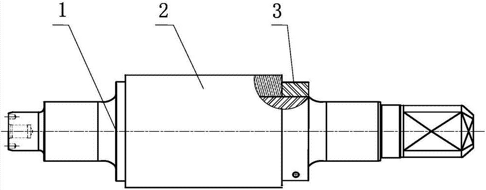
[0054] The cemented carbide composite roll with a lock nut at one end, the specific implementation steps are as follows:

[0055] 1. Set the roller ring 2 on the roller shaft 1, the gap between the roller ring and the roller shaft is matched, and one side of the roller ring is positioned by the roller shaft;

[0056] 2. Screw in the nut 3 and install it on the other side of the roller shaft, and the nut is close to the roller ring along the axial direction;

[0057] 3. Apply axial pressure to the end face of the roller ring, so that the roller ring moves in the axial direction, and the distance between the nut and the roller ring increases;

[0058] 4. The rotating nut moves to the roller ring and fits closely with the roller ring;

[0059] 5. Remove the axial pressure;

[0060] 6. The nut applies an axial compressive force of 100-200 MPa to the end face of the roller ring to fix the roller ring on the roller shaft. The obtained composite roll is as figure 1 shown.

[006...

Embodiment 2

[0063] The cemented carbide composite roll with a lock nut at one end, the specific implementation steps are as follows:

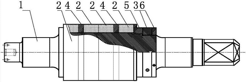
[0064] 1. If Figure 4 As shown, first put the cemented carbide roll ring 2 and the pressing ring 5 on the roll shaft 1 sequentially, and the gap fit is adopted between the roll ring, the pressing ring and the roll shaft. The above hard alloy roll ring can also be one or A plurality of roller rings, spacer rings 4 can be placed between a plurality of roller rings (such as figure 2 shown). One side of the roller ring (a plurality of roller rings refers to the outermost roller ring) is positioned by the roller shaft;

[0065] 2. Set the lock nut 3 on the other side of the roller shaft, and the nut is close to the compression ring along the axial direction, so that the nut and the compression ring are pre-locked.

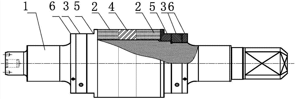
[0066] 3. If Figure 5 As shown, a pressurizing device 7 is installed behind the lock nut 3, and the pressurizing device is fixedly connected...

Embodiment 3

[0073] One end has the cemented carbide composite roll of locking nut, concrete implementation step 1-7 is the same as embodiment 2, also comprises the following steps:

[0074] 8. Install a stop nut 6 on the outside of the lock nut of the roller shaft and tighten it to form a double nut lock to prevent the lock nut from loosening during long-term service and further improve the reliability of use. The obtained easy-to-install and easy-to-unload composite rolls are as follows: figure 2 shown.

[0075] The disassembly method of the above embodiment is as follows: apply an axial pressure to the compression ring to create a gap between the lock nut and the compression ring; loosen the back nut, lock nut, remove the axial pressure, and then remove Back nuts, lock nuts, compression rings, roller rings.


PUM


Abstract

The invention provides a composite roll. The composite roll comprises a roll shaft and roll rings arranged on the roll shaft in a sleeving manner. The roll shaft and the roll rings are in clearance fit. A nut is arranged at the position, on one side of each roll ring, of the roll shaft and is closely attached to the corresponding roll ring, and axial pressing force is applied to the roll rings by the nut. The invention further relates to a preparation method of the above composite roll. The preparation method comprises the following steps that A, the roll rings are arranged on the roll shaft in the sleeving manner, and the roll rings and the roll shaft are in clearance fit; B, the nuts are screwed in and mounted on one side of the roll shaft, and the nuts are attached to the roll rings in the axial direction; C, axial pressure is applied to the end faces of the roll rings, the roll rings can move in the axial direction, and the distance between each nut and the corresponding roll ring is increased; D, each nut is rotated to move towards the corresponding roll ring and is closely attached to the corresponding roll ring; E, the axial pressure is removed; and F, the nuts apply the axial pressing force to the end faces of the roll rings, and the roll rings are fixed to the roll shaft. The rolling torque is transmitted.

Description

technical field [0001] The invention belongs to the field of manufacturing metal rolling rolls, and relates to a roll with a composite structure used in a hot rolling mill or a cold rolling mill and a preparation method thereof, in particular to a cemented carbide composite roll for steel rolling and a manufacturing method thereof. Specifically, the present invention provides a composite roll with a unique structural design and a manufacturing method. The composite roll adopts clearance fit and end face compression to transmit torque, and the key is to use ordinary nuts for locking. The composite roll of this structure has the advantages of few accessories, simple structure, easy manufacture, high reliability, and easy disassembly. Background technique [0002] It has been nearly half a century since Canadian STELCO first tried hard alloy rolls (rings) on the world's first twist-free high-speed wire rod mill produced by Morgan Corporation of the United States in 1966, and it...

Claims


Application Information

Patent Timeline
Patent Type & Authority Applications(China)
IPC IPC(8): B21B27/03
CPCB21B27/03B21B27/00
Inventor 曾守富肖辉王晓灵斯晓华
Owner ZIGONG CEMENTED CARBIDE CORP
Why Eureka
Try Eureka