Cooling fluid filtration cycle system

A circulation system and coolant technology, applied in metal processing machinery parts, maintenance and safety accessories, metal processing equipment, etc., can solve the problems of liquid slag, easy blockage, separation and other problems in the circulation system, so as to improve the filtering effect and save energy. Cost, good filtering effect

Inactive Publication Date: 2017-10-03
YANGTZE NORMAL UNIVERSITY
View PDF4 Cites 4 Cited by
  • Summary
  • Abstract
  • Description
  • Claims
  • Application Information

AI Technical Summary

Problems solved by technology

[0005] Aiming at the deficiencies of the above-mentioned prior art, the present invention provides a cooling liquid filtration circulation system to solve the technical problem that the circulation system in the prior art cannot carry out liquid slag separation and is easy to block, and can filter the cooling liquid to separate the cooling liquid. The waste residue in the liquid, so as to avoid the blockage of the cooling liquid circulation system; the filtration efficiency is high, and the filtration effect is excellent

Method used


Image

  • Cooling fluid filtration cycle system
  • Cooling fluid filtration cycle system
  • Cooling fluid filtration cycle system

Examples


Embodiment Construction

[0027] The present invention will be further described in detail below in conjunction with the accompanying drawings and preferred embodiments.

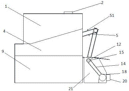
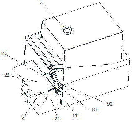
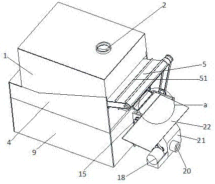
[0028] Such as Figure 1 to Figure 7 As shown, a cooling liquid filtration circulation system includes a first liquid storage tank 1, a first filter tank 4, and a second liquid storage tank 9 connected sequentially from top to bottom; the first liquid storage tank 1 is provided with The liquid inlet interface 2; the front end of the second liquid storage tank 9 communicates with the second filter box 21 through the liquid guide groove 92; the front end of the first filter box 4 exceeds the front end of the second liquid storage tank 9; the first filter A conveyor belt is provided in the case 4, and the conveyor belt includes a main drive roller 7, a slave drive roller 6 and a conveyor belt 5 provided with a screen hole; the front and rear ends of the main drive roller 7; the axis of the main drive roller 7 is located outside the fro...


PUM


Abstract

The invention discloses a cooling fluid filtration cycle system. The cooling fluid filtration cycle system comprises a first fluid storage tank, a first filtering tank and a second fluid storage tank which sequentially communicate with one another from top to bottom. The second fluid storage tank communicates with a second filtering tank through a fluid guide tank. A transfer belt is arranged inside the first filtering tank and further comprises a driving roller, a driven roller and a conveying belt with sieve holes. The driving roller and the driven roller are connected to the front end and the rear end of the first filtering tank in a rotating mode correspondingly. A magnetic roller is arranged at a fluid inlet of the second filtering box and is further located below a fluid guide tank outlet. The axis of the magnetic roller is located at the outer side of the edge of the fluid guide tank outlet. A material receiving plate is arranged at the outer side of the magnetic roller. A scraper blade is connected along the inner side edge of the material receiving plate. The scraper blade makes contact with the circumferential face of the magnetic roller. A fluid discharging connector is arranged on the outer wall of the second filtering tank. By means of the cooling fluid filtration cycle system, cooling fluid can achieve multi-level filtration, direct filtration and indirect filtration are combined, and the filtering effect is good; and meanwhile the effect of deslagging while filtration is achieved, and filtering efficiency is high.

Description

technical field [0001] The invention relates to the technical field of machining, in particular to a recycling system for filtering cooling liquid used in machining. Background technique [0002] In the process of cutting metal materials, the machine tool needs to use coolant to cool the cutting tool to prolong the service life of the tool. Generally, a large flow rate of coolant of 1000-1500L / min is required. It is a pity to discharge the coolant directly after use, and Increase the cost of mechanical processing, also can cause environmental pollution. [0003] Therefore, a circulation system is usually used, that is, the coolant sprayed from the nozzle splashes to the tool, then falls back into the groove, and then recycled, but during the machining process, the tool will drop the cut chips into the In the tank filled with coolant, it is easy to bring some fine chips into the circulation system, causing blockage of the cooling circulation system and affecting the machinin...

Claims


Application Information

Patent Timeline
Patent Type & Authority Applications(China)
IPC IPC(8): B23Q11/10
CPCB23Q11/10B23Q11/1069
Inventor 黎方军王涛
Owner YANGTZE NORMAL UNIVERSITY
Why Eureka
Try Eureka