Hanging system

A suspension system and connecting arm technology, applied in the field of mobile robots, can solve problems such as difficult to meet high performance requirements, achieve the effects of reducing labor intensity and part of the capital expenditure, improving competitiveness, and stable and efficient working conditions

Inactive Publication Date: 2017-10-03
UNIV OF ELECTRONICS SCI & TECH OF CHINA
View PDF5 Cites 13 Cited by
  • Summary
  • Abstract
  • Description
  • Claims
  • Application Information

AI Technical Summary

Problems solved by technology

Currently the most widely used suspension system, its parameters are a compromise value determined by taking into account all the performance of mobile robots. It is difficult to meet high performance requirements when the vehicle speed, load and road conditions change greatly.

Method used


Image

  • Hanging system
  • Hanging system
  • Hanging system

Examples


Embodiment 1

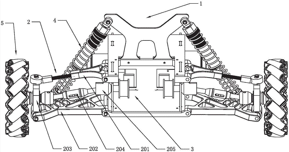
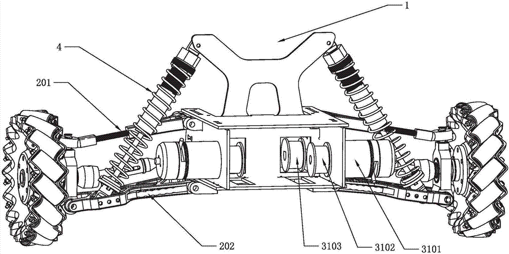
[0031] like figure 1 and figure 2 As shown, the suspension system includes a chassis 1, a connecting module 2, a power module 3, a shock absorber 4 and a Mecanum wheel 5, and the connecting module 2 includes an upper connecting arm 201 and a lower connecting arm 202 arranged in parallel, and the upper connecting arm 201 One end and one end of the lower connecting arm 202 are movably connected with the chassis 1, the other end of the upper connecting arm 201 and the other end of the lower connecting arm 202 are connected with the side connector 203, and the two ends of the shock absorber 4 are connected with the chassis 1 and the connecting module 2 respectively. It is movably connected, and the shaft end of the power module 3 is connected with the mecanum wheel 5 through the side connecting piece 203 .

[0032] The side connecting piece 203 is parallel to the corresponding surface of the chassis 1, and the side connecting piece 203 forms a parallelogram structure with the ch...

Embodiment 2

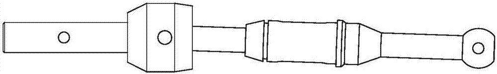
[0041] like Figure 5 and Figure 7 As shown, the suspension system and figure 1 Compared with the first embodiment shown, the difference is that the power module 3 in this embodiment includes a motor 3201, the motor 3201 passes through the chassis 1 and is connected to the driving bevel gear 3202, and the driving bevel gear 3202 and the driven bevel gear 3203 cooperate with each other , the driven bevel gear 3203 is connected with the mecanum wheel 5 through the universal joint 204 . The motor 3201 drives the driving bevel gear 3202 to rotate, and when the driving bevel gear 3202 rotates, it drives the driven bevel gear 3203 to rotate, and the driven bevel gear 3203 drives the mecanum wheel 5 to rotate through the universal joint 204 .

[0042] The driving bevel gear 3202 and the driven bevel gear 3203 are arranged perpendicular to each other, the motor 3201 drives the driving bevel gear 3202 to rotate, and the driving bevel gear 3202 and the driven bevel gear 3203 are clos...

Embodiment 3

[0045] like Figure 8 and Figure 9 As shown, the suspension system and figure 1 Compared with the first shown embodiment, the difference is that one end of the shock absorber 4 in this embodiment is movably connected with the chassis 1, and the other end of the shock absorber 4 is movably connected with the side connector 203; the upper connecting arm 201 includes The first upper connecting arm 2301 and the second upper connecting arm 2302, the lower connecting arm 202 includes the first lower connecting arm 2303 and the second lower connecting arm 2304; the power module 3 includes a motor 3301, and the motor 3301 is installed on the side connecting member 203, The motor 3301 is located between the first lower connecting arm 2303 and the second lower connecting arm 2304 .

[0046] The rotating shaft of the motor 3301 passes through the side connector 203 and is connected with the mecanum wheel 5 through a coupling;

[0047]One end of the first upper connecting arm 2301 and...


PUM


Abstract

The invention discloses a hanging system. The hanging system comprises a chassis, connecting modules, a power module, shock absorbers and Mecanum wheels, wherein each connecting module comprises an upper connecting arm and a lower connecting arm which are arranged in parallel; one end of each upper connecting arm and one end of the corresponding lower connecting arm are movably connected with the chassis, and the other end of each upper connecting arm and the other end of the corresponding lower connecting arm are connected with a corresponding side connecting piece; two ends of each shock absorber are respectively and movably connected with the chassis and the corresponding connecting module; and shaft ends of the power module respectively penetrate through the corresponding side connecting piece to be connected with the corresponding Mecanum wheel. According to the hanging system provided by the invention, the transmission is accurate, assembling and disassembling are convenient, and the operation is stable; and the hanging system has the advantages of being simple in structure, convenient to operate, stable in operation and the like.

Description

technical field [0001] The invention belongs to the technical field of mobile robots, and in particular relates to a suspension system. Background technique [0002] The suspension system is an important part of the mobile robot chassis platform, which directly affects the operational stability and safety of the robot movement, and is often used as one of the criteria for evaluating the performance of mobile robots. Currently the most widely used suspension system, its parameters are a compromise value determined by taking into account all the performance of mobile robots, and it is difficult to meet high performance requirements when the vehicle speed, load and road conditions change greatly. Contents of the invention [0003] The object of the present invention is to solve the above problems and provide a suspension system that is simple, reliable and highly stable. [0004] In order to solve the above-mentioned technical problems, the technical solution of the present ...

Claims


Application Information

Patent Timeline
Patent Type & Authority Applications(China)
IPC IPC(8): B60G3/20B60G15/02
CPCB60G3/20B60G15/02B60G2200/422B60G2202/31B60G2206/011B60G2300/50
Inventor 何俐萍顾思明王楠王中天黄智恒杨旭江
Owner UNIV OF ELECTRONICS SCI & TECH OF CHINA
Why Eureka
Try Eureka