Aircraft

A technology of aircraft and wire mesh, applied in the field of aircraft, can solve problems such as crashworthiness, easy deformation, fuselage damage, etc.

Active Publication Date: 2017-10-03
ZHUHAI PANLEI INTELLIGENT TECH CO LTD
View PDF6 Cites 1 Cited by
  • Summary
  • Abstract
  • Description
  • Claims
  • Application Information

AI Technical Summary

Problems solved by technology

At present, the protective cover of the UAV has defects such as slow dynamic response, not crashworthy, easy to deform, large mass, and limited protection capability. The rigid impact on the cover will be directly transmitted to the fuselage, causing damage to the fuselage, and even damage the electronic components inside the fuselage

Method used


Image

  • Aircraft
  • Aircraft
  • Aircraft

Examples


no. 1 example

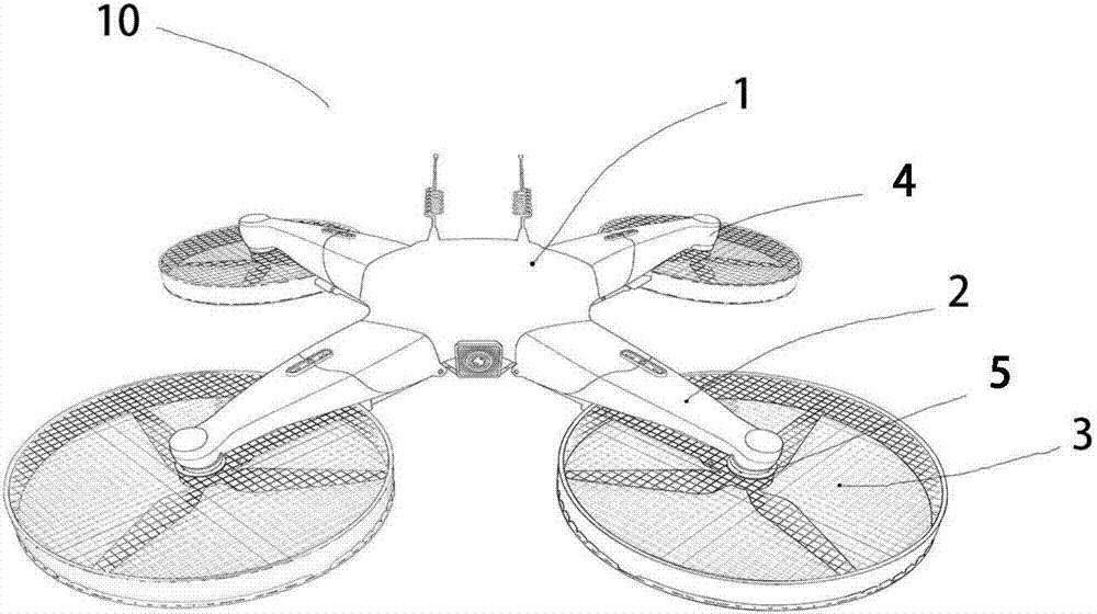
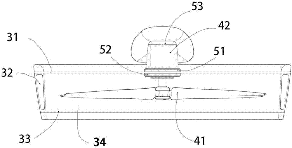
[0027] like figure 1 , figure 2 As shown, the aircraft 10 mainly includes a fuselage 1 , an arm 2 , a protective frame 3 , a power unit 4 and a mount 5 . Wherein the protective frame 3 includes the upper wire mesh 31, the side wall protective frame 32 and the lower mesh wire 33; the power unit 4 includes the driving rotor 41, the driving motor 42; the mounting seat 5 includes the mounting seat 51, the mounting plate 52 and the power mounting seat 53 . The upper wire mesh 31 , the side wall protection frame 32 and the lower wire mesh 33 are combined to form an accommodation space 34 of the power protection frame 3 ; the driving rotor 41 is placed in the accommodation space 34 and does not contact with the surroundings. The driving rotor 41 is installed on the rotating shaft of the driving motor 42, the driving motor 42 is placed in the power mounting seat 53, and the driving motor 42 and the power mounting seat 53 are installed on the mounting seat simultaneously. The upper...

no. 2 example

[0034] The difference between this embodiment and the first embodiment lies in the structure of the offline network.

[0035] like Figure 7 As shown, a support ring 8 is arranged in the middle of the lower wire mesh 332, and thread holes (not shown) for threading are processed on the side wall protection frame 322 and the support ring 9, and the pull wires are criss-crossed and run through the side wall protection frame 322 and the support ring 9 Between them, a lower wire mesh 332 is formed, and there are gasket sleeves (not shown) at the contact places between the pull wires and the holes. The seal between the gasket sleeve and the lower wire mesh 332 and the side wall protection frame 322 is completely sealed to prevent airflow from passing through the small holes on the frame form jitter. Setting the support ring 9 facilitates the installation of the aircraft drive rotor 412 .

[0036] preferred, such as Figure 8 As shown, the support ring 82 is provided with a mounti...

no. 3 example

[0039] The difference between this embodiment and the first embodiment lies in the mechanism arrangement and control of the power unit.

[0040] like Figure 9 As shown, the arms and power units are evenly distributed or symmetrically distributed on both sides of the aircraft 500 along the circumference of the aircraft 500 . The diameter of the driving rotor of the first power unit 503 is larger than the diameter of the driving rotor of the second power unit 505 , and is arranged along the general direction of the length of the fuselage 501 . The first arm 502 has a longer wheelbase than the second arm 504 and is arranged along the length of the fuselage 501 . The arm 504 is hinged to the fuselage 501 through a hinge axis, and the hinge axis is arranged along the width direction O of the arm 504 . By controlling the second arm 504, the second arm 504 can be tilted up or down to form a V-shaped structure. It can be seen that the flight maneuverability of the aircraft 500 is ...


PUM


Abstract

The invention provides an aircraft. The aircraft comprises aircraft arms, protective frames and power units, wherein the protective frames are mounted on an aircraft body through mounting bases; and the protective frames have the advantages of being high in rigidity, low in mass, high in crash-resistance and capable of reducing damage of rigid impact to the power units and the aircraft body. According to the aircraft disclosed by the invention, the defects that a conventional aircraft protective cover is low in strength, easy in deformation, short in service life and low in interchangeability, and rigid impact can easily damage the power units and the aircraft body, are overcome.

Description

technical field [0001] The invention relates to an aircraft, in particular to an aircraft with a protective frame. Background technique [0002] Aircraft include unmanned aerial vehicles and manned aerial vehicles. Unmanned aerial vehicles are referred to as "drones" for short, which are unmanned aircraft controlled by radio remote control equipment or embedded programs. At present, the rotor UAV is widely used. Its power comes from the lift provided by the high-speed rotation of the rotor. By controlling the different rotation speeds of each rotor, different actions such as lifting and hovering of the UAV can be realized. [0003] Early unmanned aerial vehicles did not have protective measures. The high-speed rotating rotor brought lift but also brought certain hazards to nearby creatures and buildings. Therefore, a rotor protective cover appeared later. Among them, the rotor protective cover and the aircraft. The connection methods include direct connection and indirect c...

Claims


Application Information

Patent Timeline
Patent Type & Authority Applications(China)
IPC IPC(8): B64C27/00B64C27/08B32B9/00B32B9/04B32B17/02B32B17/12B32B17/10B32B27/34B32B27/06B32B1/06B32B33/00
CPCB64C27/006B64C27/08B32B3/08B32B5/26B32B9/007B32B17/067B32B17/10B32B27/06B32B27/34B32B33/00B32B2307/51B32B2307/71B32B2307/558B32B2262/101B32B2262/106B64U10/10B64U50/19B64U30/20
Inventor 何春旺
Owner ZHUHAI PANLEI INTELLIGENT TECH CO LTD
Why Eureka
Try Eureka