
a dust collector

A dust collector and dust removal device technology, applied in the direction of smoke removal, chemical instruments and methods, mechanical cleaning, etc., can solve the problems of easy contamination of dust, low efficiency, high labor cost, etc., to improve the installation speed and stability, convenient and fast Installation and disassembly, the effect of improving work efficiency

Active Publication Date: 2018-09-25
CPI YUANDA ENVIRONMENTAL PROTECTION ENG
View PDF7 Cites 0 Cited by
  • Summary
  • Abstract
  • Description
  • Claims
  • Application Information

AI Technical Summary

Problems solved by technology

[0002] The fabric is mostly made of natural fibers or synthetic fibers. During the processing, the fabric is easily contaminated with wool ash. Therefore, it needs to be dedusted when it is wound into a roll. Traditional fabric dedusting requires workers to hold a sticky stick on the surface of the fabric to clean it. , but this method is time-consuming, labor-intensive, inefficient, and labor-intensive, and winding and dust removal need to be divided into two steps, which takes a long time

Method used


Image

  • a dust collector
  • a dust collector
  • a dust collector

Examples


Embodiment Construction

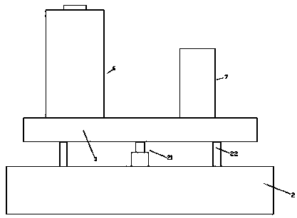
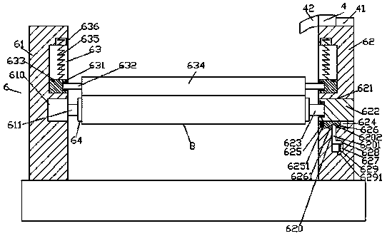
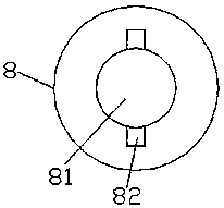
[0022] Such as Figure 1-Figure 6 As shown, a dust remover of the present invention includes a machine base 5 and a winding device 6 fixed on the left and right sides of the top surface of the machine base 5 and an introduction dust removal device 7 respectively. The winding device 6 is opposite from front to back and It is composed of a first stand 61 and a second stand 62 fixedly arranged on the top surface of the machine base 5, and the opposite sides of the first stand 61 and the second stand 62 are provided with first sliding grooves 63, a first sliding block 631 is provided in each of the first sliding grooves 63, and the rear of the first stand 61 below the first sliding groove 63 in the first stand 61 A winding motor 610 is fixed inside the side, and the right side of the winding motor 610 is connected with a first rotating shaft 611. The third sliding connection groove 621 is provided, and the inner bottom surface of the third sliding connection groove 621 is provide...


PUM


Abstract

The present invention discloses a novel dust remover. The novel dust remover comprises a machine base as well as a winding device and a lead-in and dust removing device which are respectively fixed at the left side and right side of the top surface of the machine base; the winding device is composed of a first upright frame and a second upright frame which are opposite to each other in an anterior-posterior direction and are fixedly arranged at the top surface of the machine base; first sliding connection slots are correspondingly formed at the opposite sides of the first upright frame and the second upright frame; one first sliding connection block is arranged in each first sliding connection slot; a winding motor which is located below the first sliding connection slots in the first upright frame is arranged in the rear side surface of the first upright frame; the right side surface of the winding motor is in matched connection with a first rotation shaft; a sliding connection slot which passes through the front side and the rear side of the second upright frame is formed in the second upright frame opposite to the winding motor; a guide connection slot is formed at the bottom surface of the sliding connection slot; and a second sliding connection block is in matched connection with the interior of the sliding connection slot. The novel dust remover of the invention is simple in structure; the installation and disassembly speed of a winding core can be improved; an overall winding process can be improved; automatic control on fixed-quantity winding work is realized; and the quality of fabric can be improved.

Description

technical field [0001] The invention relates to the technical field of dust removal, in particular to a dust collector. Background technique [0002] The fabric is mostly made of natural fibers or synthetic fibers. During the processing, the fabric is easily contaminated with wool ash. Therefore, it needs to be dedusted when it is wound into a roll. Traditional fabric dedusting requires workers to hold a sticky stick on the surface of the fabric to clean it. , but this method is time-consuming and labor-intensive, with low efficiency and high labor costs, and the winding and dust removal need to be divided into two steps, which takes a long time. Contents of the invention [0003] The technical problem to be solved by the present invention is to provide a dust collector, which can solve the above-mentioned problems in the prior art. [0004] The present invention is achieved through the following technical solutions: a dust remover of the present invention includes a mach...

Claims


Application Information

Patent Timeline
Patent Type & Authority Patents(China)
IPC IPC(8): D06G1/00B08B15/04B65H18/10B65H19/30
CPCB08B15/04B65H18/10B65H19/30D06G1/00
Inventor 贾君祥
Owner CPI YUANDA ENVIRONMENTAL PROTECTION ENG
Learn More