Dredging robot and application method thereof

A technology of robots and silt, applied in the direction of earth movers/excavators, waterway systems, water supply devices, etc., can solve problems such as unsatisfactory cleaning of hidden dangers, affecting people's normal travel and life, and failure to perform normal functions. To achieve the realization of intelligent automatic operation, high-quality application effect, and ensure the effect of normal progress or retrogression

Pending Publication Date: 2017-10-03
FUJIAN QUANZHOU HIT RES INSTIUTE OF ENG & TECH
View PDF8 Cites 14 Cited by
  • Summary
  • Abstract
  • Description
  • Claims
  • Application Information

AI Technical Summary

Problems solved by technology

During the use of culverts, gutters, and open channels, plastic bags, cloth, branches, hair and other sundries will be mixed in, accompanied by sediment settlement, resulting in blockage of drainage channels, which cannot function normally after being blocked. If it cannot be discharged normally, it will cause damage to the road, and the water level of the open channel is too high to overflow the channel, affecting people's normal travel and life
Highway culverts, sewers, and small open channels, etc., can’t be dredged by large-scale equipment when they are blocked, and it is difficult to clean them. They are often cleaned manually and with simple equipment, which consumes a lot of manpower and is dangerous.
[0003] When the existing silt suction trucks are used for dredging culverts, gutters, and open channels, the sand is easy to deposit and cannot be sucked clean, and it is necessary to manually hold the silt suction port for operation. There will be great risks and hidden dangers during dredging. The cleaning effect is not ideal

Method used


Image

  • Dredging robot and application method thereof
  • Dredging robot and application method thereof
  • Dredging robot and application method thereof

Examples


Embodiment Construction

[0037] The specific implementation manners of the present invention will be further described below with reference to the accompanying drawings.

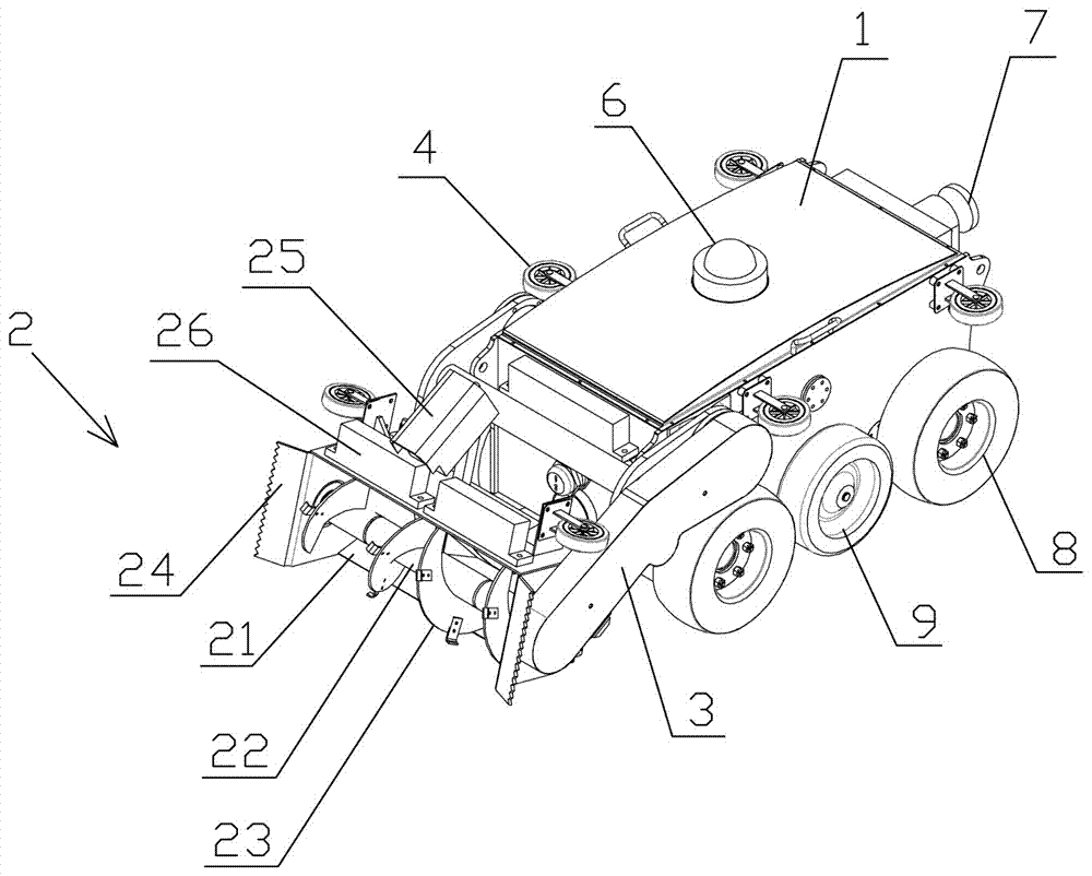
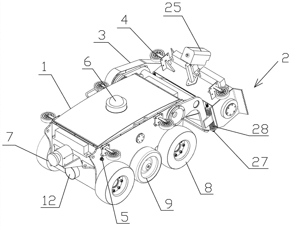
[0038] Such as Figure 1 to Figure 5As shown, a dredging robot includes a car body 1, a working device 2 for crushing and collecting sludge, and a lifting mechanism 3 for adjusting the working installation position of the working device 2. The lifting mechanism 3 Installed at the front end of the car body 1, the working device 2 is movably mounted on the lifting mechanism 3; the front side wall of the car body 1 is provided with a mud inlet 11, the car body 1 is provided with a conveying pipe 12 on the rear end side wall, and the interior of the car body 1 is provided with a penetrating conveying pipe (not shown in the figure due to the viewing angle), and the front end of the penetrating conveying pipe communicates with the mud inlet 11 , the rear end of the penetrating conveying pipe communicates with the conveying pipe 12, the f...


PUM


Abstract

The invention discloses a dredging robot and an application method thereof. The dredging robot comprises a vehicle, a working device and a lifting mechanism, wherein the working device is used for crushing and collecting silt, the lifting mechanism is used for movably regulating the work and mounting positions of the working device, the lifting mechanism is mounted at the front end of the vehicle, and the working device is movably mounted on the lifting mechanism in a matched manner; the front-end lateral wall of the vehicle is provided with a silt inlet, a conveying pipe is arranged on the rear-end lateral wall of the vehicle, a penetrating conveying pipe is arranged inside the vehicle, the front end of the penetrating conveying pipe is communicated with the silt inlet, the rear end of the penetrating conveying pipe is communicated with the conveying pipe, the front end of the silt inlet is communicated with the working device, and the conveying pipe is connected with a silt suction pump for sucking and conveying the silt. The dredging robot has the advantages that the robot can replace workers to perform dredging and can convey the silt out of culverts, sewers and open channels, intelligent and automatic operation can be achieved, and the robot is high in work efficiency and convenient to operate.

Description

technical field [0001] The present invention relates to the field of intelligent mechanical equipment, more specifically to a dredging robot and its usage method. Background technique [0002] Culverts refer to drainage channels (water passages) built under the roadbed and built below the road surface in order to make the road pass through the canal smoothly without hindering traffic in the construction of highway engineering. Through this structure, water can flow through the road below. The gutter is to cover the gutter with a cover, and such a gutter is called a gutter. Usually refers to a drainage ditch with a small distance from the ground surface. During the use of culverts, gutters, and open channels, plastic bags, cloth, branches, hair and other sundries will be mixed in, accompanied by sediment settlement, resulting in blockage of drainage channels, which cannot function normally after being blocked. If it cannot be discharged normally, it will cause damage to the...

Claims


Application Information

Patent Timeline
Patent Type & Authority Applications(China)
IPC IPC(8): E03F7/10E02F5/28
CPCE02F5/282E03F7/10
Inventor 张伟李瑞峰陶金陈俊宏梁培栋陈文桂
Owner FUJIAN QUANZHOU HIT RES INSTIUTE OF ENG & TECH
Why Eureka
Try Eureka