
Bidirectional pounding tuned mass damper

A technology of control devices and limit devices, which is applied in the direction of building types, buildings, building components, etc., can solve the problems of inability to dissipate system kinetic energy, amplify local responses, and reduce vibration damping effects, so as to suppress bad vibration effects and reduce Dynamic response, effect of reducing load

Active Publication Date: 2017-10-03
SHANDONG UNIV
View PDF4 Cites 3 Cited by
  • Summary
  • Abstract
  • Description
  • Claims
  • Application Information

AI Technical Summary

Problems solved by technology

However, this type of device also has obvious defects: first, the suspended mass pendulum lacks an energy dissipation mechanism and cannot dissipate the absorbed system kinetic energy; second, when the natural frequency of the suspended mass pendulum is close to the natural frequency of the main structure, the vibration is reduced The effect is better, if the difference between the two is large, the vibration reduction effect will be greatly reduced, and even the phenomenon of amplifying the local response will appear
However, this vibration damping device also has its limitations: the mass of the traditional collision damper mass itself is relatively large, and there is a danger of amplifying the acceleration response of the structure during collision, which is likely to cause local damage to the structure itself; in addition, the collision process will cause Noise pollution affects normal life

Method used


Image

  • Bidirectional pounding tuned mass damper
  • Bidirectional pounding tuned mass damper
  • Bidirectional pounding tuned mass damper

Examples


Embodiment Construction

[0034] It should be pointed out that the following detailed description is exemplary and intended to provide further explanation to the present application. Unless defined otherwise, all technical and scientific terms used herein have the same meaning as commonly understood by one of ordinary skill in the art to which this application belongs.

[0035] It should be noted that the terminology used here is only for describing specific implementations, and is not intended to limit the exemplary implementations according to the present application. As used herein, unless the context clearly dictates otherwise, the singular is intended to include the plural, and it should also be understood that when the terms "comprising" and / or "comprising" are used in this specification, they mean There are features, steps, operations, means, components and / or combinations thereof.

[0036] Embodiments of the present invention will be described in detail below in conjunction with technical solu...


PUM


Abstract

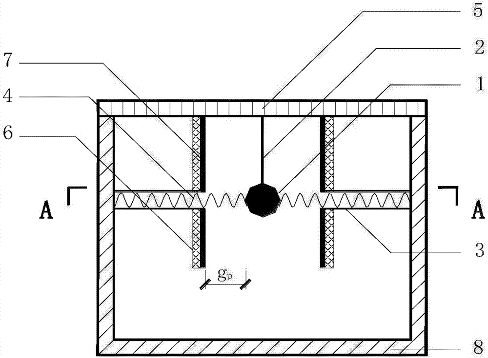
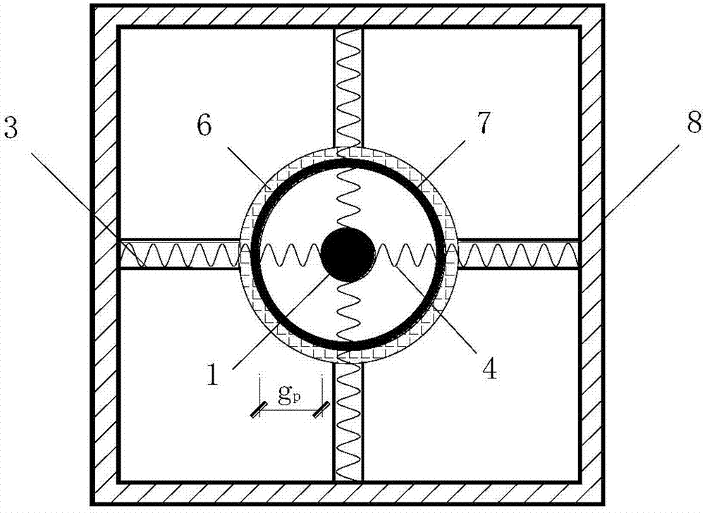
The invention discloses a bidirectional pounding tuned mass damper which is suitable for being mounted at the top of a large-span or high-rise structure. The bidirectional pounding tuned mass damper comprises a mass block, a pendulum line, sleeves, springs, a connection plate, a limiting device, an adhesive elastic material layer and a chamber. The mass block and the pendulum line for a suspended mass pendulum. The bidirectional pounding tuned mass damper is capable of absorbing kinetic energy of a main structure through the suspended mass pendulum and also colliding with the limiting device in a pendulum process to result in energy exchange and consumption of the kinetic energy absorbed by the suspended mass pendulum, so that structural dynamic response can be lowered, and dual damping control effects are achieved; in addition, by the adhesive elastic material layer on the limiting device, collision energy consumption capacity is increased. The bidirectional pounding tuned mass damper is clear in principle, simple in structure, small in space occupancy, high in resistance to external interferences, remarkable in inhibition of undesirable vibration effects, capable of reducing dynamic response in multiple directions, high in safety, low in manufacturing cost and high in economic and social benefits, thereby having a promising application prospect.

Description

technical field [0001] The present invention relates to the field of building structures, specifically a bidirectional pounding tuned mass damper (BPTMD for short), which is mainly used for vibration control of important building structures such as large spans and high towers. Background technique [0002] In recent years, many high-rise and super-high-rise structures with complex shapes and variable internal spaces have emerged in my country. These structures have a series of notable characteristics such as large size, complex functions, and novel shapes. As the height of the building increases, horizontal loads including horizontal seismic action and wind load become the main factors controlling the design of the structure. At present, the most important goal emphasized by my country's technical standards and norms is to prevent structures from being damaged and collapsed under the action of earthquakes. However, the Wenchuan Earthquake showed that although many building ...

Claims


Application Information

Patent Timeline
Patent Type & Authority Applications(China)
IPC IPC(8): E04B1/98E04H9/02E04H9/14
CPCE04B1/98E04H9/02E04H9/14
Inventor 田利张欣荣坤杰张鹏
Owner SHANDONG UNIV
Learn More