
Absorption heat pump

An absorption heat pump and absorption liquid technology, applied in the field of absorption heat pump, can solve the problems of restricted setting conditions, height increase, and high height of absorption heat pump, and achieve the effect of high assurance

Active Publication Date: 2017-10-03
EBARA REFRIGERATION EQUIP & SYST
View PDF7 Cites 0 Cited by
  • Summary
  • Abstract
  • Description
  • Claims
  • Application Information

AI Technical Summary

Problems solved by technology

[0004] Since the absorption heat pump described in Patent Document 1 is arranged so that the gas phase part of the vertically long gas-liquid separator is at a higher position than the uppermost part of the main structure, the overall height of the absorption heat pump becomes too high, and due to the long The horizontal cross-sectional area of ​​the gas-liquid separator is relatively small, so the volume required for gas-liquid separation is ensured above the upper limit liquid level that should correspond to a relatively large liquid level change, so that the height is further increased, resulting in the setting conditions being restricted. restrict

Method used


Image

  • Absorption heat pump
  • Absorption heat pump
  • Absorption heat pump

Examples


Embodiment Construction

[0023] Hereinafter, embodiments of the present invention will be described with reference to the drawings. In addition, in each figure, the same or similar reference numerals are assigned to mutually identical or corresponding components, and overlapping descriptions will be omitted.

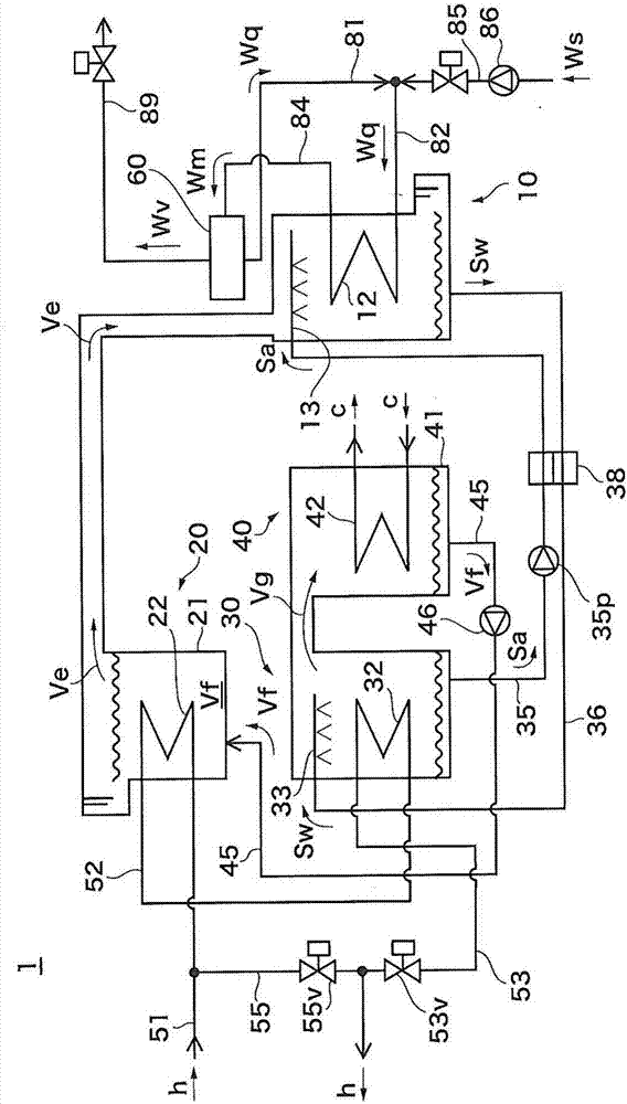
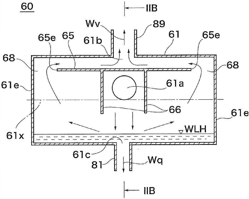
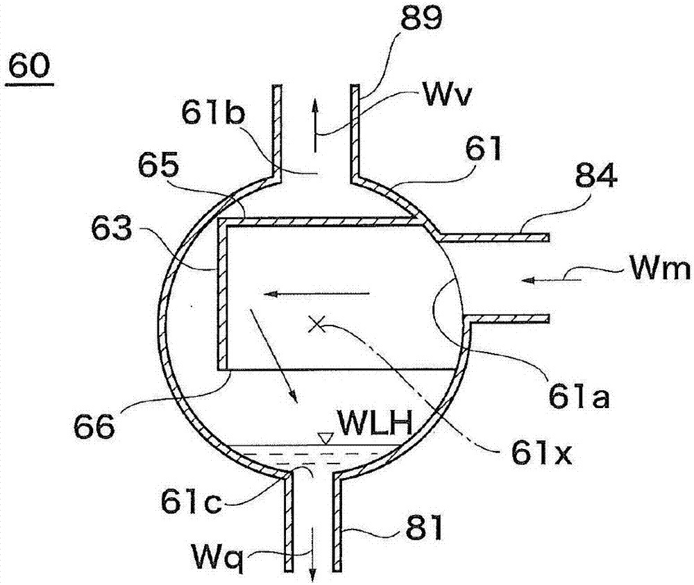
[0024] First, refer to figure 1 The absorption heat pump 1 according to the embodiment of the present invention will be described. figure 1 is a schematic system diagram of the absorption heat pump 1 . The absorption heat pump 1 includes an absorber 10 , an evaporator 20 , a regenerator 30 , and a condenser constituting main equipment for an absorption heat pump cycle of an absorption liquid S (Sa, Sw) and a refrigerant V (Ve, Vg, Vf). 40, and a gas-liquid separator 60 is also provided.

[0025] In this specification, the absorption liquid is referred to as "dilute solution Sw", "concentrated solution Sa", etc. according to its properties and positions on the heat pump cycle in order to easil...


PUM


Abstract

The invention discloses an absorption heat pump which includes an absorber which uses the absorption heat which is generated when an absorption liquid absorbs steam of a coolant and generates a mixed fluid and also a gas-liquid separator (60). The gas-liquid separator (60) includes: a canister (61) is longer in the horizontal direction; a collision wall (63) which enables a mixed fluid (Wm) which flows from an inflow opening (61a) to the canister (61) to have collision; a detour forming road (65) which forms a detour which can increase the stroke of a fluid which collides with the collision wall (63) and reaches a outflow opening (61b), wherein the inflow opening (61a), the outflow opening (61b), and the collision wall (63) are formed at positions higher than a highest liquid level (WLH). The detour forming road (65) is configured to enable the fluid which has collided the collision wall (63) to circumvent the end part (65e) of the detour forming part (65) in the horizontal direction. A through flow path (68) for the fluid to go through is formed at the end part (65e) and between the detour forming part (65) and the canister (61).

Description

technical field [0001] The present invention relates to absorption heat pumps, and more particularly to absorption heat pumps with suppressed height. Background technique [0002] There is a second type of absorption heat pump as a heat source machine that takes in a heated medium whose temperature is higher than that of a driving heat source. The second type of absorption heat pump has, as its main structure, an evaporator that evaporates the refrigerant liquid, an absorber that absorbs the refrigerant vapor with the absorption liquid, a regenerator that separates the refrigerant from the absorption liquid, and a condenser that condenses the refrigerant vapor. In the absorber, the heat generated when the absorption liquid absorbs the refrigerant vapor can be used to heat the liquid of the heated medium and evaporate it, and a gas-liquid separator is also provided, which introduces the heated heated medium and separates it into heated Medium steam and liquid. As such an ab...

Claims


Application Information

Patent Timeline
IPC IPC(8): F25B15/02F25B43/00
CPCF25B15/02F25B43/00Y02A30/27Y02B30/62
Inventor 竹村与四郎山田宏幸
Owner EBARA REFRIGERATION EQUIP & SYST
Learn More