Hub mold rim water cooling device

A wheel hub mold and cooling device technology, applied in the field of mechanical casting, can solve the problems of long casting cycle, prolong casting cycle, low production efficiency, etc., and achieve the effects of reducing scrap rate, shortening casting cycle, and improving production efficiency

Pending Publication Date: 2017-10-10
KUNSHAN ZHONGYITE MACHINERY IND
View PDF6 Cites 2 Cited by
  • Summary
  • Abstract
  • Description
  • Claims
  • Application Information

AI Technical Summary

Problems solved by technology

[0004] Existing low-pressure casting molds for automotive aluminum wheels do not have cooling systems at the hot joints of the spoke corners and the rear hanger. cycle, low production efficiency
It can be seen that if the hot nodes are not cooled quickly, it will lead to local looseni

Method used


Image

  • Hub mold rim water cooling device
  • Hub mold rim water cooling device
  • Hub mold rim water cooling device

Examples


Embodiment approach 1

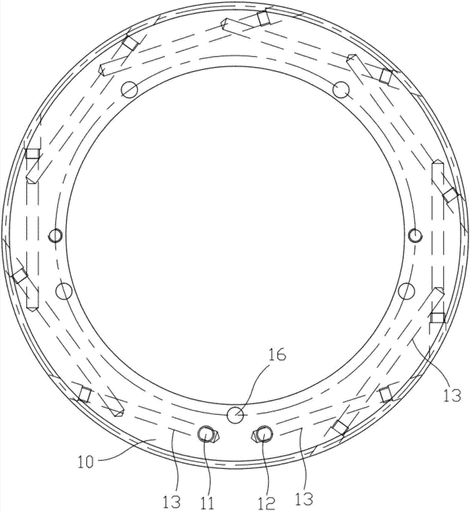
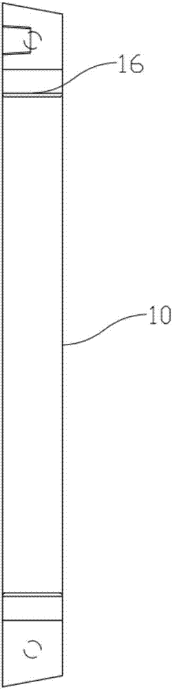
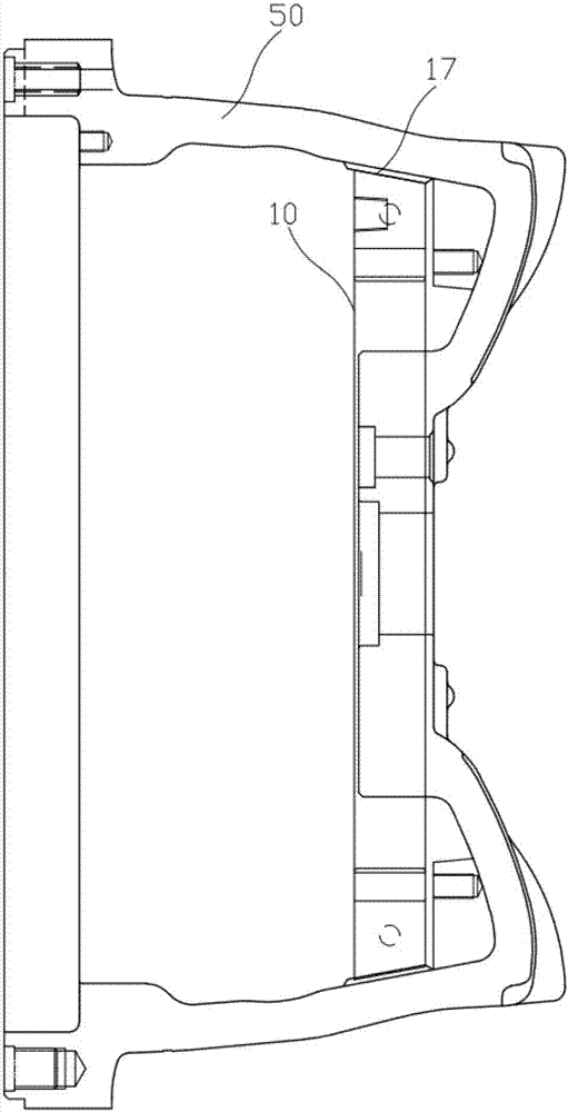
[0027] like Figures 1 to 3 As shown, the wheel hub mold tire ring water cooling device of the present invention is used to be installed at the hot node of the upper mold of the wheel hub mold (the area formed by the junction of the upper mold and the side mold is the hot node of the cast wheel hub), including The upper mold 50 of the mold is coaxial and can be installed on the ring-shaped tire ring body 10 at the thermal node of the upper mold 50. The tire ring body 10 is provided with a water inlet 11 and a water outlet 12 next to each other, and a water inlet 11 and an outlet connected to each other. The cooling water channel of the nozzle 12, and the cooling water channel is close to the outer wall of the tire ring body 10 in contact with the upper mold 50.

[0028] Specifically, the cooling water channel is formed by cross-connecting a plurality of long holes 13 drilled along the outer wall of the tire ring body 10 in turn, and the ends of the long holes 13 at the head an...

Embodiment approach 2

[0035] like Figures 4 to 6 As shown, the wheel hub mold tire ring water cooling device of the present invention is used to be installed at the hot node of the upper mold of the wheel hub mold (the area formed by the junction of the upper mold and the side mold is the hot node of the cast wheel hub), including The upper mold 50 of the mold is coaxial and can be installed on the ring-shaped tire ring body 20 at the thermal node of the upper mold 50. The tire ring body 20 is provided with a water inlet 21 and a water outlet 22 next to it, and a water inlet 21 and an outlet. The cooling water channel of the nozzle 22, and the cooling water channel is close to the outer wall of the tire ring body 20 in contact with the upper mold 50.

[0036] Specifically, the cooling water channel is an annular groove 23 recessed on the tire ring body 20 and coaxial with the tire ring body 20. The annular groove 23 is arc-shaped and its two ends are connected with the water inlet 21 and the water...


PUM


Abstract

The invention discloses a hub mold rim water cooling device. The device comprises an annular rim body which is coaxial with an upper mold of a hub mold and can be mounted on an upper mold hot joint; the rim body is provided with a water inlet and a water outlet which are next to each other and further provided with a cooling water way communicating with the water inlet and the water outlet; and the cooling water way is close to the outer wall, making contact with the upper mold, of the rim body. According to the cooling device, through the cooling water way in the rim body, when a hub is cast, the hot joint of the upper mold is cooled, thus the portion, away from a pouring port, of a casting can be solidified firstly, then the portion, close to the pouring port, of the casting is solidified, and finally the pouring port is solidified; the defect that the after-solidification position and the hot joint position cannot obtain material replenishing, thus shrinkage cavities occur, or loosening is caused is avoided, the rejection rate of the castings is decreased, and the production efficiency is improved accordingly; and meanwhile the mold is cooled, and the casting period can be shortened.

Description

technical field [0001] The invention relates to the technical field of mechanical casting, in particular to a tire ring water cooling device for a wheel hub mold. Background technique [0002] As one of the most important moving parts of a car, the wheel hub has high requirements on its performance, weight and service life. At present, aluminum alloy wheels stand out in the automotive industry for their light weight, fast heat dissipation, good shock absorption performance, long life, and good balance. [0003] Aluminum alloy wheels are generally produced by casting. The molds for casting wheels mainly include upper molds, lower molds, side molds and bases. After the molds, lower molds and side molds are combined, the casting cavity of the wheel hub to be cast is formed. Both the mold and the side molds are fixed on the base. During casting, the cavity is filled with material from the sprue located on the lower mold. During the solidification process after pouring, the are...

Claims


Application Information

Patent Timeline
IPC IPC(8): B22D18/04B22D27/04
CPCB22D18/04B22D27/04
Inventor 叶成高翔张传勇
Owner KUNSHAN ZHONGYITE MACHINERY IND
Why Eureka
Try Eureka