Paper manufacturing cutting device

A cutting device and paper technology, which is applied in metal processing and other directions, can solve the problems of unreasonable structural design of the cutting device, poor flexibility of the cutting device, poor paper edge flatness, etc., and achieve fast cutting speed, simple internal structure and stable cutting. Effect

Inactive Publication Date: 2017-10-10
许四清
0 Cites 2 Cited by

AI-Extracted Technical Summary

Problems solved by technology

[0003] 1. The structural design of the cutting device is unreasonable. During the cutting process, the paper will appear on the knife. When the equipment is abnormal, the cutting knife will generate a large cutting force, and the knife will...

Abstract

The invention discloses a paper manufacturing and cutting device, comprising a swing rod, a push-pull rod and a cutting box, the inner surface wall of the cutting box is movably sleeved with a fixed shaft through a bearing, and the fixed shaft is fixed at the center of the swing rod, The side of the pendulum rod close to the upper end is welded with a positioning column, the positioning column is sleeved with the column groove, the column groove is arranged on one side of the disc, and the power shaft is fixed at the center of the disc. The other side of the power shaft is connected with a motor, and the motor is fixed on the inner surface wall of the cutting box through a fixed base, and the bottom end of the swing rod is fixedly connected with a separation sleeve, and the center of the separation sleeve is movable. There is a movable shaft. This paper manufacturing cutting device uses the integrity and gravity of the paper and the reciprocating motion of the pendulum rod to cut the paper into paper of the same size. The cutting speed is fast and the cutting is stable. During the cutting process, the return spring ensures the cutting. The safety of the cutting knife is avoided by excessive force.

Application Domain

Technology Topic

EngineeringPaper manufacturing +3

Image

  • Paper manufacturing cutting device
  • Paper manufacturing cutting device
  • Paper manufacturing cutting device

Examples

  • Experimental program(1)

Example Embodiment

[0020] The technical solutions in the embodiments of the present invention will be clearly and completely described below in conjunction with the accompanying drawings in the embodiments of the present invention. Obviously, the described embodiments are only a part of the embodiments of the present invention, rather than all the embodiments. Based on the embodiments of the present invention, all other embodiments obtained by those of ordinary skill in the art without creative work shall fall within the protection scope of the present invention.
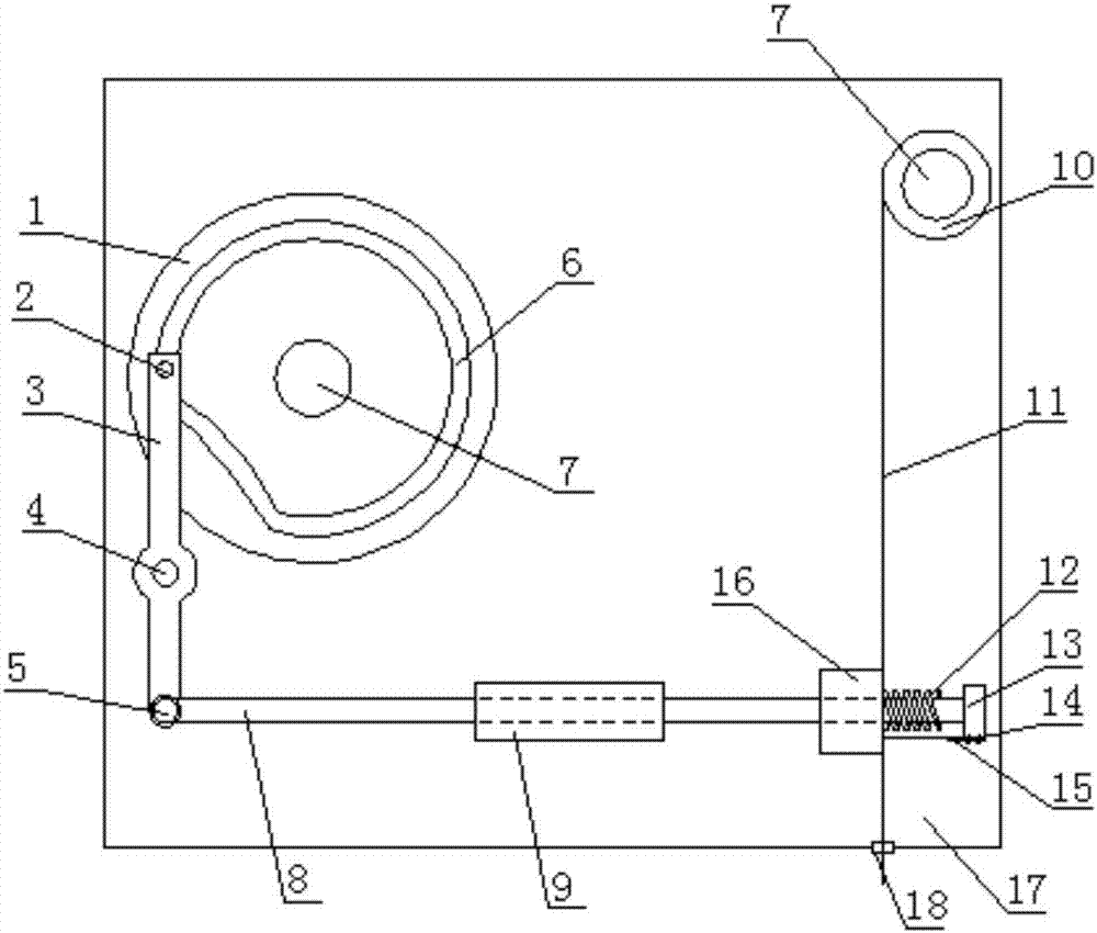
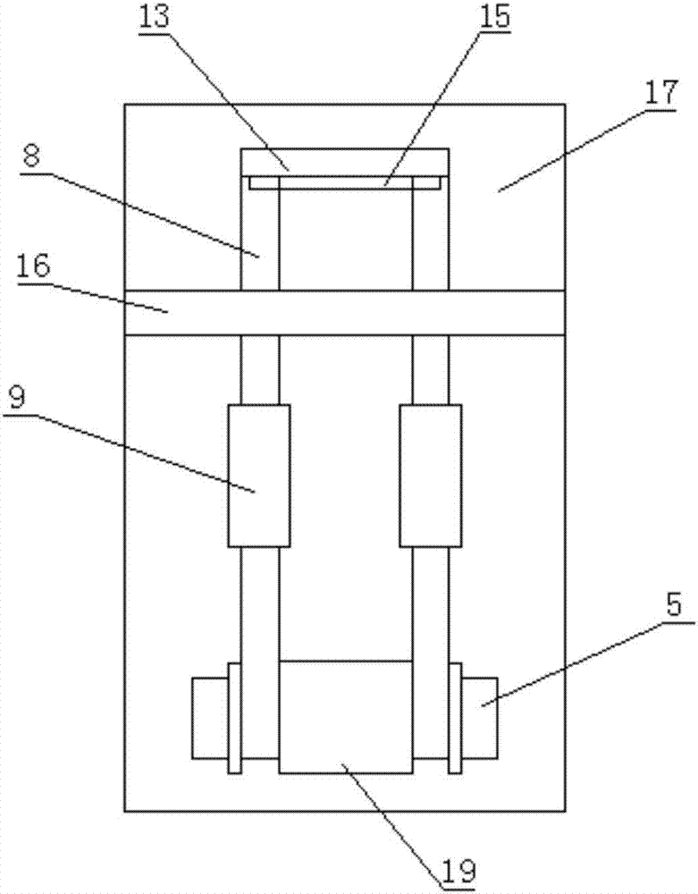
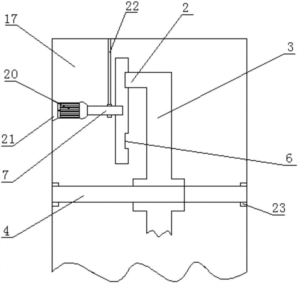
[0021] See Figure 1-4 The present invention provides a technical solution: a paper manufacturing cutting device, comprising a swing rod 3, a push-pull rod 8 and a cutting box 17, the inner surface of the cutting box 17 is movably sleeved with a fixed shaft 4 through a bearing 23, so The fixed shaft 4 is fixed at the center of the pendulum rod 3. A positioning pillar 2 is welded on the side of the pendulum rod 3 close to the upper end, and the positioning pillar 2 is sleeved with the pillar groove 6, and the pillar groove 6 is arranged in a circle. On one side of the disc 1, a power shaft 7 is fixed at the center of the disc 1, and a motor 20 is connected to the other side of the power shaft 7, and the motor 20 is fixed to the inner surface of the cutting box 17 through a fixed base 21 The bottom end of the pendulum rod 3 is fixedly connected with a separating sleeve 19, a movable shaft 5 is sleeved at the center of the separating sleeve 19, and a push-pull rod 8 is sleeved on both sides of the movable shaft 5, so The outer surface wall at the center of the push-pull rod 8 is sheathed with a guide post 9, and a cutting board 16 is sheathed on one side of the guide post 9 through the push-pull rod 8. The cutting board 16 is fixed on the inner surface wall of the cutting box 17. The end of the tie rod 8 is welded with a cutter fixing block 13, and the lower end of the cutter fixing block 13 is screwed with a cutting knife 15 through a fastening bolt 14, and the inner surface of the cutting box 17 is sleeved with a power shaft 7 through a bearing 23, A paper roll 10 is fixed on the outer wall of the power shaft 7, a paper 11 is wound on the outer wall of the paper roll 10, and the paper 11 passes through the space between the two push-pull rods 8 and the slot 18 respectively.
[0022] The outer surface wall of the power shaft 7 at the center of the disc 1 is movably sleeved with a bearing 23, a suspension rod 22 is fixed above the bearing 23, and the upper surface wall of the suspension rod 22 is fixed to the upper surface wall of the cutting box 17, Play the role of support. There are two guide posts 9 in total, and push-pull rods 8 are movably sleeved at the centers of the two guide posts 9, and the guide posts 9 are fixed inside the cutting box 17, mainly for guiding and The role of the fixed position, the width of the column slot 6 is equal to the diameter of the positioning column 2, the disk 1 can use the column slot 6 to drive the positioning column 2 to move during the rotation process, the motor 20 and The external power supply is electrically connected, and a return spring 12 is fixed on one side of the cutting board 16, and the return spring 12 is sleeved on the outer wall of the push-pull rod 8.
[0023] Working principle: When the paper cutting device is used, the paper 11 is rolled on the outer wall of the paper roll 10, and then the paper 11 is passed through the middle position of the two push-pull rods 8 and the slot 8, and then the motor 20 is connected to the external power supply. Electrically connected, under the action of the power shaft 7, the paper roll 10 and the disc 1 perform a rotating movement, and the disc 1 drives the pendulum rod 3 to swing through the column slot 6, and under the action of the force, the push-pull rod 8 pushes and pulls Movement, through the guiding action of the guide post 9 and the cutting board 16, the cutting knife 15 moves left and right, and cuts the paper 11 during the movement, and falls out of the slot 18.
[0024] Although the embodiments of the present invention have been shown and described, those of ordinary skill in the art can understand that various changes, modifications, and substitutions can be made to these embodiments without departing from the principle and spirit of the present invention. And variations, the scope of the present invention is defined by the appended claims and their equivalents.

PUM

no PUM

Description & Claims & Application Information

We can also present the details of the Description, Claims and Application information to help users get a comprehensive understanding of the technical details of the patent, such as background art, summary of invention, brief description of drawings, description of embodiments, and other original content. On the other hand, users can also determine the specific scope of protection of the technology through the list of claims; as well as understand the changes in the life cycle of the technology with the presentation of the patent timeline. Login to view more.

Similar technology patents

Cutting device of building metal pipes

Owner:成都科启新力科技有限公司

Notching machine

ActiveCN102009394AFast cutting speedDimensionally stable processingGrinding devicesEngineeringMachining
Owner:沈阳中科超硬磨具磨削研究所

Block producing machine based on coldness dispelling and warm tonifying food

ActiveCN108835198AFast cutting speedIncrease the speed of threadingMeat shaping/cuttingParallel plateMechanical engineering
Owner:龙庄润集团有限公司

Diamond saw blade material and manufacturing process

PendingCN108149098AGood cutting effectFast cutting speedUltra fineNickel
Owner:JIANGSU SUPER PEAK TOOLS CO LTD

Classification and recommendation of technical efficacy words

  • Fast cutting speed
  • Cutting stability

Convenient-to-fix cutting device

InactiveCN107598610APrevent swingingCutting stabilityFeeding apparatusLarge fixed membersEngineeringDrive wheel
Owner:无锡宝威焊割设备有限公司

Fast servo ultraprecise fly cutting machining method for brittleness material complex curved surface

ActiveCN107052462AAvoid brittleCutting stabilitySingle degree of freedomMulti degree of freedom
Owner:TIANJIN UNIV

Nylon tube cutting fixture

Owner:CHONGQING SULIAN AUTO PARTS
Why Eureka
Try Eureka