Waste packaging box compression device for medicine packaging
A compression device and packaging technology, applied in the direction of stamping machines, presses, manufacturing tools, etc., can solve the problems of complex operation, poor compression effect, inconvenient use, etc., and achieve the effect of simple operation, good compression effect and convenient use
- Summary
- Abstract
- Description
- Claims
- Application Information
AI Technical Summary
Problems solved by technology
Method used
Image

Examples
Embodiment 1
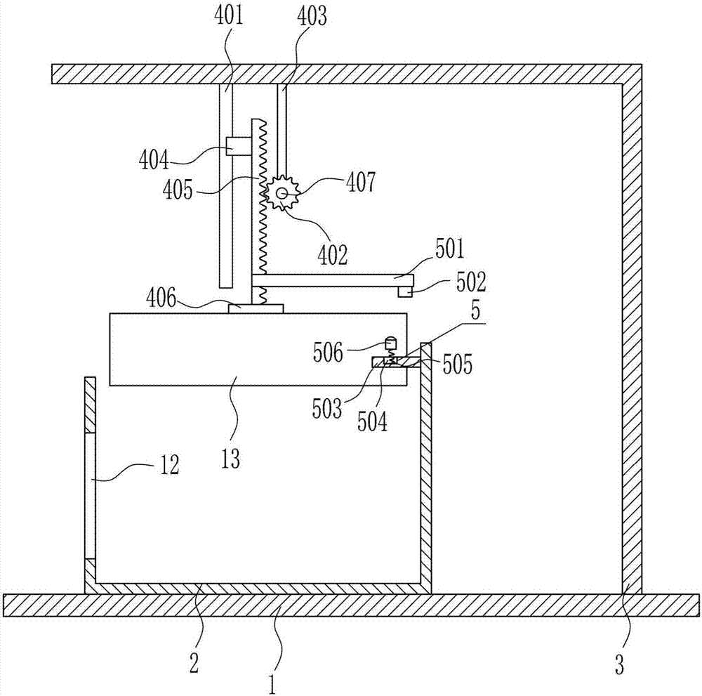
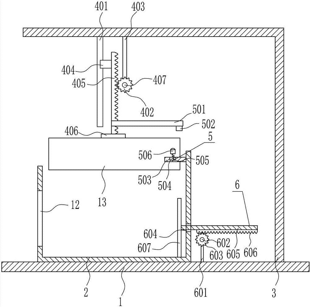
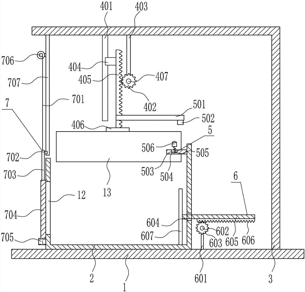
[0035] A waste packaging box compression device for medical packaging, such as Figure 1-5 As shown, it includes a bottom plate 1, a compression frame 2, a 7-type plate 3, a heavy iron block 13, a first compression device 4 and a control device 5, and the compression frame 2 and the 7-type plate 3 are welded on the left and right sides of the top of the bottom plate 1. The compression frame 2 is located on the left side of the 7-type plate 3, and the left side of the compression frame 2 has an opening 12. The top of the 7-type plate 3 is provided with a first compression device 4, and the bottom of the first compression device 4 is welded with a heavy iron block 13. The iron block 13 is located directly above the compression frame 2, and the upper right side of the compression frame 2 is provided with a control device 5. The control device 5 is located at the front side of the heavy iron block 13. The front side of the upper and lower parts on the top is connected, the touch p...
Embodiment 2
[0037] A waste packaging box compression device for medical packaging, such as Figure 1-5 As shown, it includes a bottom plate 1, a compression frame 2, a 7-type plate 3, a heavy iron block 13, a first compression device 4 and a control device 5, and the compression frame 2 and the 7-type plate 3 are welded on the left and right sides of the top of the bottom plate 1. The compression frame 2 is located on the left side of the 7-type plate 3, and the left side of the compression frame 2 has an opening 12. The top of the 7-type plate 3 is provided with a first compression device 4, and the bottom of the first compression device 4 is welded with a heavy iron block 13. The iron block 13 is located directly above the compression frame 2, and the upper right side of the compression frame 2 is provided with a control device 5. The control device 5 is located at the front side of the heavy iron block 13. The front side of the upper and lower parts on the top is connected, the touch p...
Embodiment 3
[0040] A waste packaging box compression device for medical packaging, such as Figure 1-5 As shown, it includes a bottom plate 1, a compression frame 2, a 7-type plate 3, a heavy iron block 13, a first compression device 4 and a control device 5, and the compression frame 2 and the 7-type plate 3 are welded on the left and right sides of the top of the bottom plate 1. The compression frame 2 is located on the left side of the 7-type plate 3, and the left side of the compression frame 2 has an opening 12. The top of the 7-type plate 3 is provided with a first compression device 4, and the bottom of the first compression device 4 is welded with a heavy iron block 13. The iron block 13 is located directly above the compression frame 2, and the upper right side of the compression frame 2 is provided with a control device 5. The control device 5 is located at the front side of the heavy iron block 13. The front side of the upper and lower parts on the top is connected, the touch p...
PUM
| Property | Measurement | Unit |
|---|---|---|
| Height | aaaaa | aaaaa |
| Length | aaaaa | aaaaa |
| Length | aaaaa | aaaaa |
Abstract
Description
Claims
Application Information
PatSnap Eureka turns technology decisions into work you can execute. Powered by our Innovation Knowledge Graph, it runs expert workflows across engineering, life sciences, materials and intellectual property. Get your review-ready output in minutes.


