Automatic gas cylinder filling device and method

A gas cylinder and automatic technology, which is applied in the container filling method, the installation device of the container structure, the container discharge method, etc., can solve the problems of high physical exertion of employees, high risk factor, manual operation, etc.

Active Publication Date: 2017-10-10
济宁协力能源有限公司
View PDF7 Cites 10 Cited by
  • Summary
  • Abstract
  • Description
  • Claims
  • Application Information

AI Technical Summary

Problems solved by technology

[0002] As we all know, gas cylinders are a kind of pressure vessels regardless of their size and category. The gas pressure in some cylinders reaches 15.0Mpa, which is relatively high, and many of them contain dangerous components such as flammable, explosive, a

Method used


Image

  • Automatic gas cylinder filling device and method
  • Automatic gas cylinder filling device and method
  • Automatic gas cylinder filling device and method

Examples


Embodiment 1

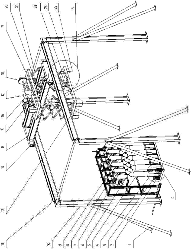
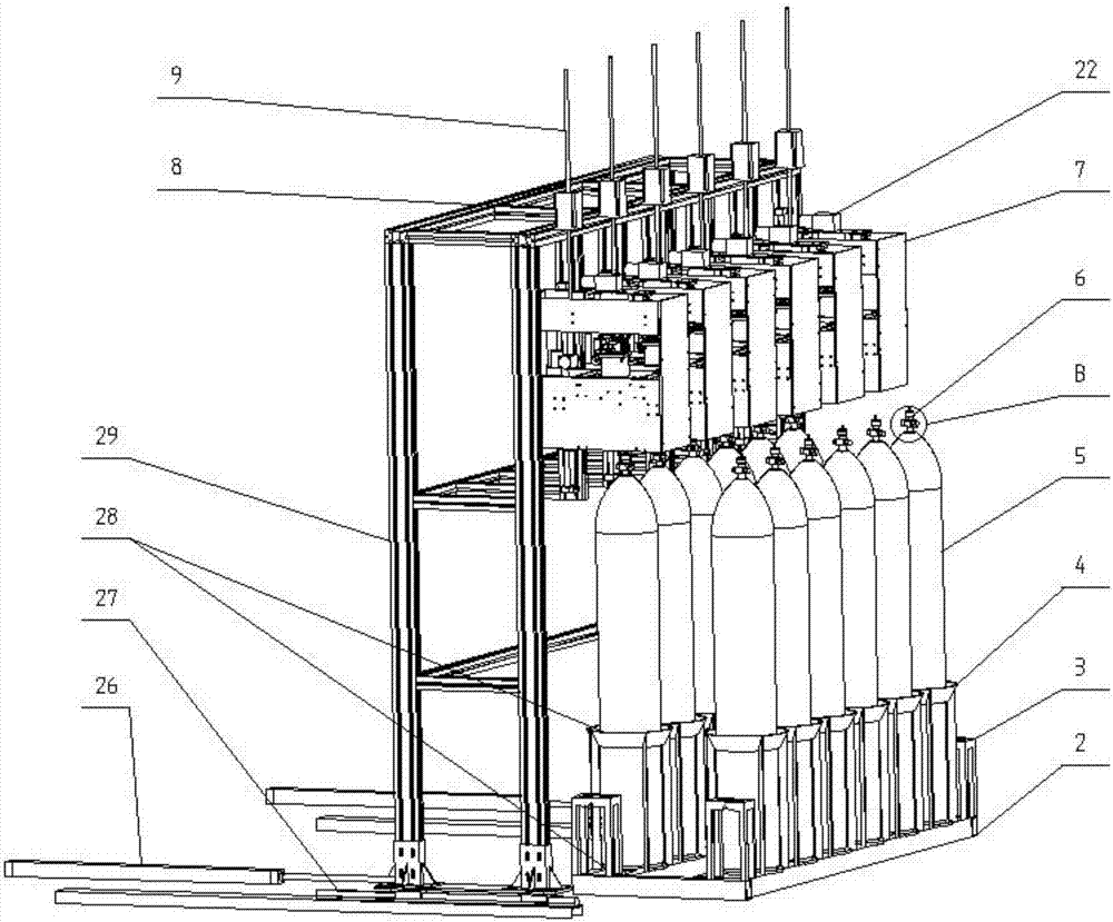
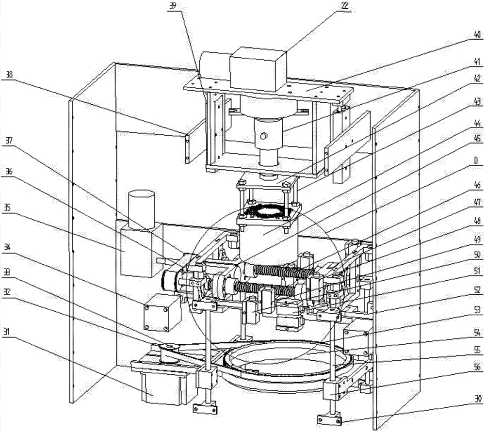
[0041] Such as Figure 1 to Figure 8 The gas cylinder automatic filling device shown includes a filling frame 29, a gas cylinder placement frame 2 and a filling box 7, and is characterized in that a lifting drive mechanism is arranged on the filling frame 29, and the lower end of the lifting drive mechanism is connected to the filling box 7 A bottle valve switch mechanism, a bottle valve detection and filling mechanism and a gas cylinder rotation mechanism are installed in the filling box 7 sequentially. The device also includes a PLC controller, a lifting drive mechanism, a bottle valve switch mechanism, a bottle valve detection and filling mechanism. The loading mechanism and the cylinder rotating mechanism are respectively connected to the PLC controller.

[0042] Both sides of the filling box 7 are provided with slide blocks, and the filling frame 29 is provided with a slide rail. The bar 9 is provided with a nut, and the nut is fixedly arranged on the filling box 7, and ...

Embodiment 2

[0056] The invention provides a method for automatically filling a gas cylinder, the method comprising the following steps:

[0057] The first step: put the gas cylinder 5 on the gas cylinder rack 2;

[0058] The second step: move the gas cylinder rack 2 to the filling position of the gas cylinder 5;

[0059] Step 3: The PLC controller controls the movement of the cylinder 26 to push the filling frame 29 and the filling box 7 on it to the filling position;

[0060] Step 4: The PLC controller controls the lifting drive mechanism and the gas cylinder rotation mechanism to work, and controls the filling box 7 to descend while driving the gas cylinder 5 to rotate. After reaching the set position, the bottle valve detection filling mechanism detects and corrects the direction of the cylinder valve 6 , and along the bottle valve 6;

[0061] Step 5: The PLC controller controls the bottle valve detection and filling mechanism to clamp the bottle valve 6, then controls the bottle val...


PUM


Abstract

The invention relates to an automatic gas cylinder filling device and method, and belongs to the technical field of methods and equipment for filling pressure containers with liquefied gas or solidified gas or compressed gas. The automatic gas cylinder filling device comprises a filling frame, a gas cylinder holding frame and a filling tank, wherein the filling frame is provided with a lifting driving mechanism with the lower end connected with the filling tank, and a cylinder valve opening-closing mechanism, a cylinder valve detection filling mechanism and a gas cylinder rotating mechanism are sequentially mounted in the filling tank from top to bottom. The automatic gas cylinder filling device further comprises a PLC which is connected with the lifting driving mechanism, the cylinder valve opening-closing mechanism, the cylinder valve detection filling mechanism and the gas cylinder rotating mechanism. PLC automatic configuration is adopted, automatic filling is achieved, filling staff are isolated in the gas filling process and are prevented from being injured when dangers happen during gas filling, the labor intensity of the staff is reduced, and labor is greatly saved.

Description

technical field [0001] The invention belongs to the technical field of methods and equipment for loading liquefied, solidified or compressed gases into pressure vessels, and in particular relates to an automatic gas bottle filling device and a filling method thereof. Background technique [0002] As we all know, gas cylinders are a kind of pressure vessels regardless of their size and category. The gas pressure in some cylinders reaches 15.0Mpa, which is relatively high, and many of them contain dangerous components such as flammable, explosive, and highly toxic. The problems of stage filling of gas cylinders are as follows: the entire filling process is manual operation, which consumes a lot of energy for employees, and the direct contact between people and gas cylinders has a high risk factor. Contents of the invention [0003] The purpose of the present invention is to provide an automatic filling device for gas cylinders, which is automatically controlled by a PLC cont...

Claims


Application Information

Patent Timeline
IPC IPC(8): F17C5/00F17C5/02F17C5/06F17C13/00F17C13/02F17C13/04F17C13/08
CPCF17C5/005F17C5/02F17C5/06F17C13/00F17C13/02F17C13/025F17C13/04F17C13/084F17C2205/0107F17C2205/013F17C2205/0153
Inventor 徐勇何岩苏延才甄鹏飞陈鑫徐福强
Owner 济宁协力能源有限公司
Why Eureka
Try Eureka