Heat recycle device of heat-conducting oil boiler

A technology of heat recovery device and heat conduction oil boiler, which is applied in the field of boilers, can solve problems such as waste of energy and direct exhaustion of flue gas, and achieve the effect of improving the recovery utilization rate

Pending Publication Date: 2017-10-10
JIANGSU FENGXINYUAN IND CLOTH CO LTD
View PDF11 Cites 3 Cited by
  • Summary
  • Abstract
  • Description
  • Claims
  • Application Information

AI Technical Summary

Problems solved by technology

[0003] The purpose of the present invention is to solve the shortcoming of direct evacuation of heat conduction oil boiler flue gas and waste of energy in the prior art, and propose a heat recovery device for heat conduction oil boilers

Method used


Image

  • Heat recycle device of heat-conducting oil boiler
  • Heat recycle device of heat-conducting oil boiler
  • Heat recycle device of heat-conducting oil boiler

Examples


Embodiment Construction

[0015] The following will clearly and completely describe the technical solutions in the embodiments of the present invention with reference to the accompanying drawings in the embodiments of the present invention. Obviously, the described embodiments are only some, not all, embodiments of the present invention.

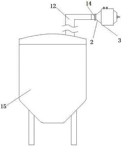
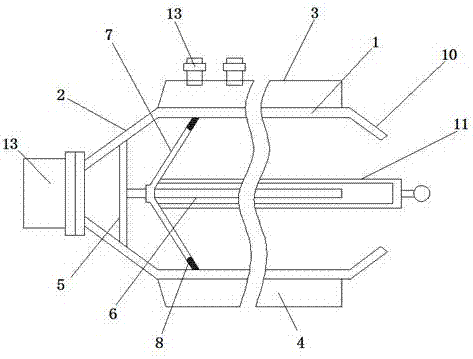
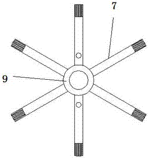
[0016] refer to Figure 1-3 , a heat recovery device for a heat-conducting oil boiler, comprising a recovery cylinder 1, the side wall of the recovery cylinder 1 is fixedly connected to an inlet shrink cover 2, and the side wall of the inlet shrink cover 2 away from the recovery cylinder 1 is fixedly connected to a flange 14, and the inlet The shrink hood 2 is sealed and connected with the flue gas pipe 13 through the connecting flange 14, the end of the flue gas pipe 13 away from the inlet shrink hood 2 is inserted into the inner cavity of the boiler 15, and the inner wall of the inlet shrink hood 2 is fixedly connected to the first fixing plate 5, the first The out...


PUM


Abstract

The invention relates to the technical field of boilers, in particular to a heat recycle device of a heat-conducting oil boiler. The heat recycle device comprises a recycle cylinder; the side wall of the recycle cylinder is fixedly connected with an inlet retraction cover; the side, far from the recycle cylinder, of the inlet retraction cover is fixedly connected with a flange; the inlet retraction cover is in seal connection with a smoke pipe by being connected with the flange; the end, far from the inlet retraction cover, of the smoke pipe is inserted into an inner cavity of the boiler; the inner wall of the inlet retraction cover is fixedly connected with a first fixed plate; a fixed rod is vertically mounted on the outer wall of the first fixed plate; the outer wall of the fixed rod is sleeved with a sleeve ring; the outer wall of the sleeve ring is fixedly connected with scrapers, and the scrapers make contact with the inner wall of the recycle cylinder; according to the heat recycle device of the heat-conducting oil boiler, waste heat in boiler smoke can be effectively absorbed and recycled, the situation that after the recycle device is used for a long time, the inner wall of the recycle cylinder adheres too much smoke duct, so that the recycle utilization rate of the recycle device is low can be prevented, and thus the heat recycle device has the high heat recycle utilization rate.

Description

technical field [0001] The invention relates to the technical field of boilers, in particular to a heat recovery device for a heat-conducting oil boiler. Background technique [0002] During the operation of the heat-conducting oil boiler, the temperature of the flue gas in the exhaust pipe can reach above 350°C, so the flue gas of the heat-conducting oil boiler contains a lot of heat, and the waste heat loss of the flue gas at the tail is relatively large, while the existing heat-conducting oil The high-temperature flue gas generated during the operation of the boiler is directly evacuated, which wastes energy and pollutes the environment. Contents of the invention [0003] The purpose of the present invention is to solve the disadvantages of direct evacuation of heat conduction oil boiler flue gas and waste of energy in the prior art, and propose a heat recovery device for heat conduction oil boilers. [0004] In order to achieve the above object, the present invention ...

Claims


Application Information

Patent Timeline
Patent Type & Authority Applications(China)
IPC IPC(8): F24H9/00F23J3/02F23J15/06
CPCF23J3/026F23J15/06F24H9/0026F24H9/0036Y02E20/30
Inventor 蔡环
Owner JIANGSU FENGXINYUAN IND CLOTH CO LTD
Why Eureka
Try Eureka