A beamforming method using signal non-circular characteristics

A non-circular characteristic, signal technology, applied in diversity/multi-antenna system, space transmit diversity, electrical components, etc., can solve the problem of loss of signal-to-noise ratio gain, inability to reduce side lobe level, increase of beam side lobe level, etc.

Active Publication Date: 2020-11-13
慧众行知科技(北京)有限公司
View PDF3 Cites 0 Cited by
  • Summary
  • Abstract
  • Description
  • Claims
  • Application Information

AI Technical Summary

Problems solved by technology

When beamforming technology is applied to some fields that require artificially modulated signals (non-circular signals), such as in the field of wireless communication, the traditional linear beamformer based on various criteria is no longer optimal, because these artificially modulated signals are non-stationary For stochastic processes, its statistical properties are no longer the same as the assumptions about the signal in the traditional linear beamformer. Only using the traditional optimal beamformer to beamform the non-stationary process cannot fully utilize all the information of the observation vector
[0004] For uniform linear arrays, increasing the number of array elements can improve the resolution of conventional beamforming methods, but cannot reduce the sidelobe level
In the case of not increasing the number of array elements, if the non-uniform weighting process is performed, although the resolution of the conventional beamforming method can be improved, the sidelobe level of the beam will increase, and at the same time, the signal-to-noise ratio will be lost.

Method used


Image

  • A beamforming method using signal non-circular characteristics
  • A beamforming method using signal non-circular characteristics
  • A beamforming method using signal non-circular characteristics

Examples


Embodiment Construction

[0021] The following knot will be combined with embodiment, the method of the present invention is further described.

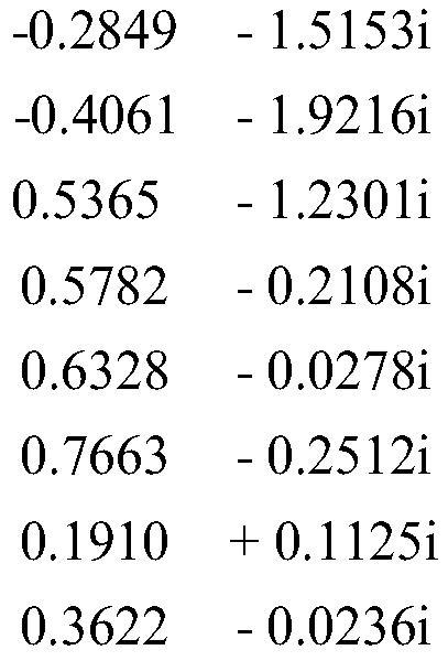
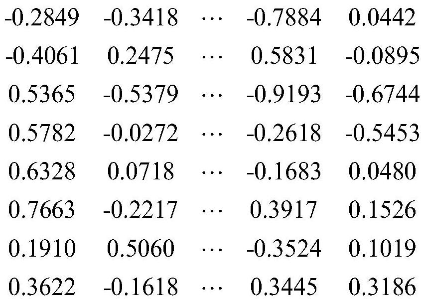
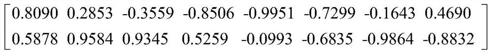
[0022] This embodiment takes a uniform linear antenna array with 8 array elements and a narrowband signal source scenario as an example. The serial numbers of the array elements are 1, 2, 3, 4, 5, 6, 7, and 8, and the default is 1 array element as the reference array element. The distances between each array element and 1 array element are 0.5 meters and 1.0 meters respectively. 1.5 meters, 2.0 meters, 2.5 meters, 3 meters, 3.5 meters. Suppose there are two mutually incoherent signal sources in the space, and their incident directions are θ 1 =7°,θ 2 =12°The signal length and non-circular phase are respectively φ s1 =72°,φ s2 = BPSK signal of 240°. The ideal spatial white noise is complex Gaussian white noise with a signal-to-noise ratio of 10dB. The sample length is 256.

[0023] The specific implementation process of the present invention is as follo...


PUM


Abstract

The invention belongs to a beam forming method in the technical field of electronic information, in particular to a beam forming method utilizing the non-circular characteristic of a signal. The method of the present invention at first carries out time-domain sampling to the received non-circular signal to obtain the observation vector; then, obtains the signal model of an extended observation vector by taking the real part and the imaginary part of the observation vector; Divide the grid by angle to obtain the weight vector matrix, and do the inner product with the extended observation vector to draw the three-dimensional direction diagram of the received signal. The estimated value of the direction of arrival and the non-circular phase; finally, the estimated value of the direction of arrival is combined with the non-circular coefficient of the signal to construct a weighted vector function of the target signal, and then obtain the desired signal pattern. The beamforming method based on the non-circular characteristics of the signal uses the non-circular characteristics to make selections and filter out interference signals, thereby significantly reducing the influence of interference on the DOA estimation of the signal of interest.

Description

technical field [0001] The invention belongs to a beam forming method in the technical field of electronic information, in particular to a beam forming method utilizing the non-circular characteristic of a signal. Background technique [0002] Beamforming uses a system composed of multiple sensor arrays in space to transmit or receive space signals. Through the weighted processing of the received information of the array, the components of the expected signal in the output of the array are received and enhanced as effectively as possible, while the interference and noise are effectively suppressed. Among the existing methods based on this principle, there are typically Minimum Variance Distortionless Response (MVDR, Minimum Variance Distortionless Response) beamforming, and Linear Multi-Constraint Minimum Variance (LCMV, Linear Constraint Minimum Variance) beamforming algorithms. [0003] Traditional linear beamformers are generally based on the simple assumption that the d...

Claims


Application Information

Patent Timeline
Patent Type & Authority Patents(China)
IPC IPC(8): H04B7/08
CPCH04B7/086
Inventor 万群刘江波董芳圆申艳妮常煜
Owner 慧众行知科技(北京)有限公司
Why Eureka
Try Eureka