Adjustable mechanical-electrical integrated cutting knife

A cutting knife, adjustable technology, applied in the direction of metal processing, etc., can solve the problems that the position cannot be changed according to actual needs, the surface of the operating table is damaged, and the height cannot be changed, so that it is not easy to shake, unstable, difficult to deviate, and easy to operate. Effect

Pending Publication Date: 2017-10-13
洪灵坪
5 Cites 15 Cited by

AI-Extracted Technical Summary

Problems solved by technology

[0003] 1. During the use of the cutting machine, the cutting knife often cannot be selected to cut at any angle. It is necessary to change the placement of the object to achieve the purpose of cutting at any angle. If the object is too large, it will cause inconvenience to the operation;
[0004] 2. The height of the operating table is often fixed, and the height cannot be changed at any time according to different operators or different placement positions. Sometimes it will cause inconvenience to the operation, and the humanization is not high enough;
[0005] 3. The cutting knife...

Abstract

The invention discloses an adjustable mechanical-electrical integrated cutting knife which comprises a workbench, an operating floor, a cutting knife body and a base. The operating floor is arranged on the upper surface of the workbench. Sliding grooves are formed in the left end and the right end of the upper surface of the operating floor. Sliding blocks are arranged in the sliding grooves. A support is fixedly arranged at the upper ends of the sliding blocks. Pins are arranged in the lower end of the support. The upper ends of the pins penetrate through the surface of the outer side of the lower end of the support. The cutting knife body can be controlled by a rotary shaft to select any angle for cutting. The purpose of cutting at any angle can be achieved without changing the placing position of an object. Operation is easy, using is convenient, the cutting efficiency is improved, the position can be changed according to actual requirements, different portions of the object can be cut conveniently during cutting, the cutting efficiency is high for an object needing to be cut repeatedly, in addition, protecting grooves corresponding to the cutting knife body are formed in the upper surface of the operating floor, the cutting knife body is not prone to damaging the surface of the operating floor, and the cutting knife is suitable for popularization.

Application Domain

Technology Topic

Image

  • Adjustable mechanical-electrical integrated cutting knife
  • Adjustable mechanical-electrical integrated cutting knife
  • Adjustable mechanical-electrical integrated cutting knife

Examples

  • Experimental program(1)

Example Embodiment

[0027] The following will clearly and completely describe the technical solutions in the embodiments of the present invention with reference to the accompanying drawings in the embodiments of the present invention. Obviously, the described embodiments are only some, not all, embodiments of the present invention. Based on the embodiments of the present invention, all other embodiments obtained by persons of ordinary skill in the art without making creative efforts belong to the protection scope of the present invention.
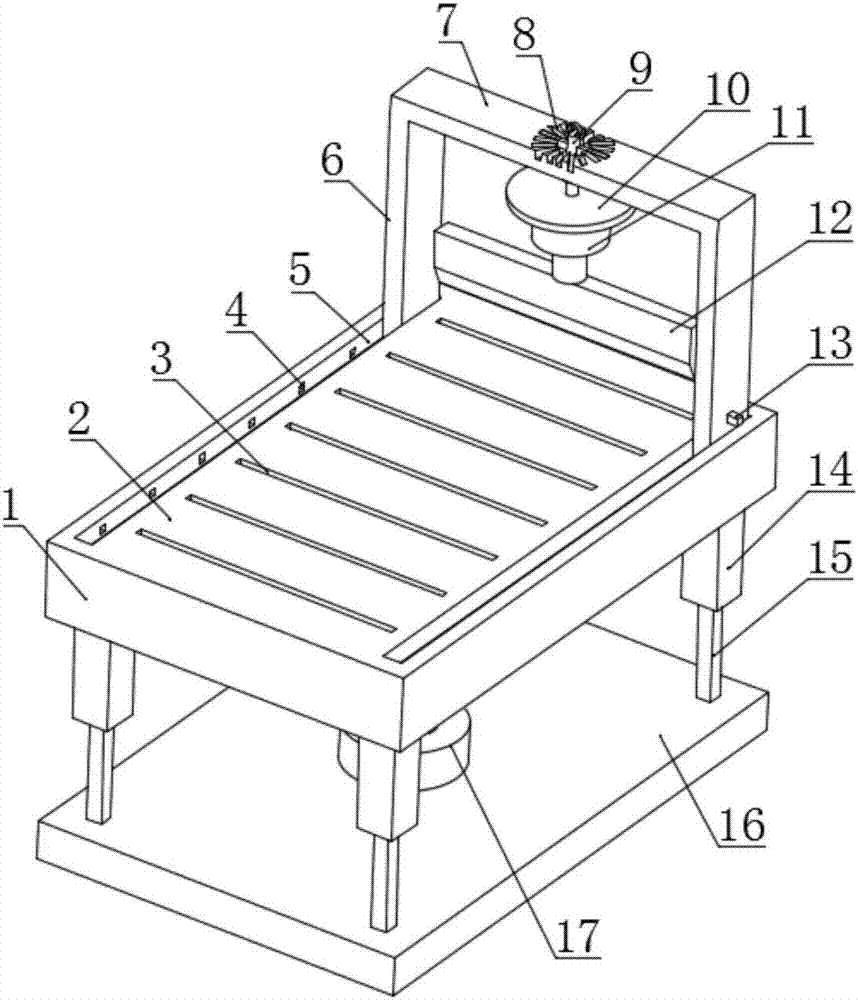
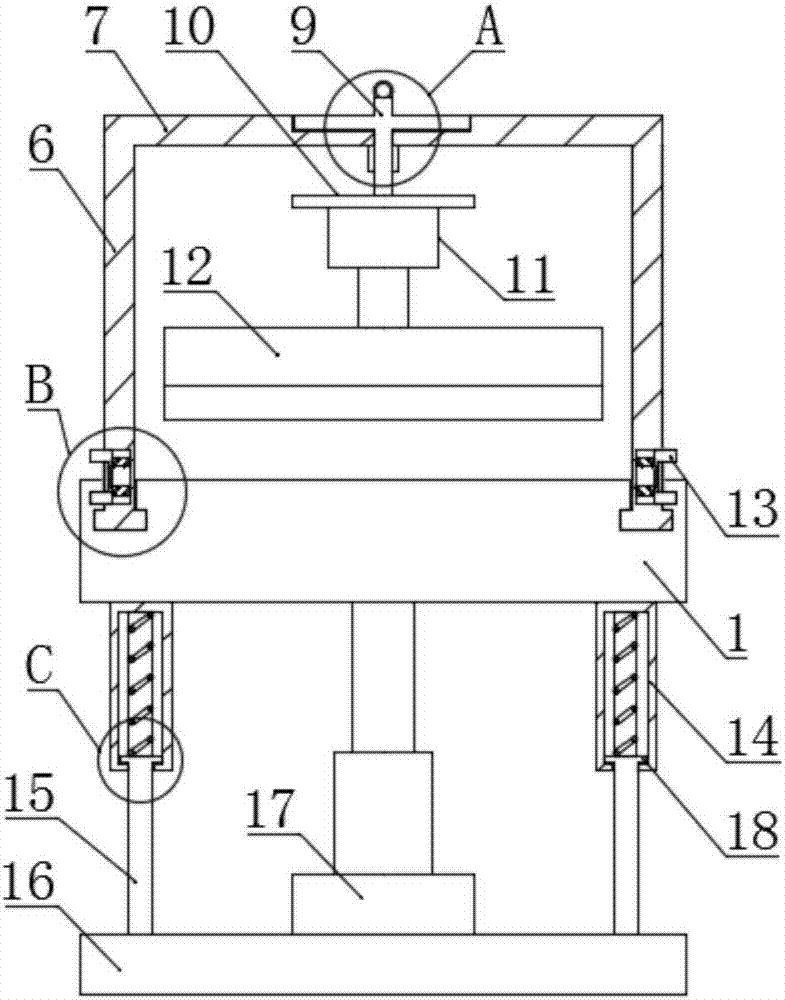
[0028] see Figure 1-6 , the present invention provides a technical solution: an adjustable mechatronic cutting knife, including a workbench 1, an operation platform 2, a cutting knife 12 and a base 16, the upper surface of the workbench 1 is provided with an operation platform 2, and the operation platform 2 The left and right ends of the upper surface are provided with chute 5, the chute 5 is provided with a slider 21, the slider 21 is in an inverted "T" shape structure, the chute 5 is in an inverted "T" shape groove structure, the slider 21 and The chute 5 can be slidably connected, the upper end of the slider 21 is fixedly provided with a bracket 6, and the lower end of the bracket 6 is provided with a pin 13 inside, and the pin 13 is in a "concave" shape structure, and the pin 13 is fixedly connected to the inside of the bracket 6 by a spring. The upper end of the pin 13 is set through the outer surface of the lower end of the support 6, the lower end of the pin 13 is set in the pin hole 4, and the pin hole 4 is set on the inner wall of the outward end of the chute 5, and the pin hole 4 is provided with multiple, and the multiple pin holes 4 are in the form of Set at equal distances and equal in size, a top plate 7 is fixed between the upper ends of the brackets 6 on both sides. The top plate 7 has a rectangular plate-like structure. A plurality of fixing grooves 8 are arranged in a circle around the rotating shaft 9 in a circular array. The upper end of the rotating shaft 9 is fixed with a fixed rod 20. The fixing rod 20 is arranged in the fixing groove 8. The upper surface of the rotating shaft 9 is also fixed with a pull ring. 19. The outer ring of the lower end of the rotating shaft 9 is provided with an external thread, and the outer thread at the lower end of the rotating shaft 9 is provided with a nut. , the fixed plate 10 is a disc-shaped structure, the fixed plate 10 is located below the top plate 7, and the height of the gap between the top plate 7 and the fixed plate 10 is greater than the sum of the height of the nut and the height of the fixed rod 20, and the fixed plate 10 is fixed on the lower surface. Be provided with lifting motor 11, be fixed with cutting knife 12 on the rotating shaft of lifting motor 11 lower ends, cutting knife 12 is located at the top of operating platform 2, and operating platform 2 upper surface is provided with a plurality of protective grooves 3, and the width of protective groove 3 and The length is consistent with the width and the length of the cutting knife 12 respectively. A plurality of pin holes 4 in the chute 5 are respectively arranged at the two ends of a plurality of protective grooves 3. A base 16 is provided below the workbench 1, and a middle position on the upper surface of the base 16 is provided. There is a cylinder 17, the cylinder telescopic rod at the upper end of the cylinder 17 is fixed in the middle of the lower surface of the workbench 1, the four corners of the upper surface of the base 16 are fixed with telescopic rods 15, the telescopic rods 15 are in the shape of a square column, and the telescopic sleeve 14 is hollow Square prism structure, telescopic bar 15 upper surface is fixedly provided with limit plate 18, and limit plate 18 is rectangular plate-like structure, and limit plate 18 is located at telescoping sleeve 14 inside, and limit plate 18 upper surface and telescoping sleeve 14 upper inner walls They are fixedly connected by springs, and the upper end of the telescopic rod 15 is covered with a telescopic sleeve 14, and the telescopic sleeve 14 is fixed on the lower surface of the workbench 1.
[0029] Working principle: First, screw down the nut at the lower end of the rotating shaft 9, and pull the pull ring 19 to drive the fixed rod 20 at the upper end of the rotating shaft 9 to move out of the fixing groove 8. At this time, the rotating shaft 9 can be rotated according to actual needs to change the cutting knife 12 The purpose of cutting angle, after adjusting the cutting angle, put down the pull ring 19, the fixing rod 20 falls in the corresponding fixing groove 8, after that, tighten the nut upwards, fix the rotating shaft 9 on the top plate 7, the structure is stable, The cutting knife 12 is not easy to shake, and the cutting accuracy is high. At this time, the lifting motor 11 controls the cutting knife 12 to move up and down to achieve the purpose of cutting objects. The upper surface of the operating table 2 is also provided with a protective groove 3 corresponding to the cutting knife 12 , the cutting knife 12 will enter the protective groove 3 when cutting to the bottom of the object, which is not easy to cause damage to the surface of the operating table 2, the service life of the equipment is long, and the maintenance cost is saved. Can achieve the purpose of cutting at any angle, easy to operate, easy to use, and improve cutting efficiency. The telescopic rod 15 moves up and down, and the overall structure remains balanced, and the limit plate 18 in the telescopic sleeve 14 avoids the phenomenon that the telescopic rod 15 falls off from the telescopic sleeve 14, and the height can be changed at any time according to different operators or different placement positions, which is convenient The operation is more user-friendly. When the pin 13 is pressed, the slider 21 can move in the chute 5. When the slider 21 moves, it can drive the bracket 6 to move. For the purpose of moving, when the position of the cutting knife 12 is adjusted, the pin 13 is loosened, and the pin 13 will be automatically engaged in the corresponding pin hole 4 in the chute 5 due to the reaction force of the spring, so that the purpose of fixing the bracket 6 is achieved, and it can Change the position according to actual needs, it is convenient to cut different positions of the object during cutting, and the cutting efficiency is high for objects that need to be cut multiple times, which is suitable for promotion.
[0030]Although the embodiments of the present invention have been shown and described, those skilled in the art can understand that various changes, modifications and substitutions can be made to these embodiments without departing from the principle and spirit of the present invention. and modifications, the scope of the invention is defined by the appended claims and their equivalents.

PUM

no PUM

Description & Claims & Application Information

We can also present the details of the Description, Claims and Application information to help users get a comprehensive understanding of the technical details of the patent, such as background art, summary of invention, brief description of drawings, description of embodiments, and other original content. On the other hand, users can also determine the specific scope of protection of the technology through the list of claims; as well as understand the changes in the life cycle of the technology with the presentation of the patent timeline. Login to view more.

Similar technology patents

Laser beam coupling output device for high-power semiconductor

InactiveCN102012567AReasonable structureReduce the difficulty of machiningPolarising elementsSemiconductor laser theoryPower semiconductor device
Owner:BEIJING UNIV OF TECH

Classification and recommendation of technical efficacy words

  • Functional
  • Reasonable structure

A ceramic insulator device for high voltage capacitor

InactiveCN101546636ALow manufacturing costReasonable structureSuspension/strain insulatorsHigh voltage capacitorsEngineering
Owner:王海龙
Why Eureka
Try Eureka