

Novel hole puncher
A punching machine, a new type of technology, is applied in the direction of paper/cardboard containers, containers, bag making operations, etc. It can solve the problems of inconvenient adjustment, time-consuming and laborious, etc., and achieve the effect of ensuring the quality of punching, simple operation, and precise adjustment
- Summary
- Abstract
- Description
- Claims
- Application Information
AI Technical Summary
Problems solved by technology
Method used
Image

Examples
Embodiment 1
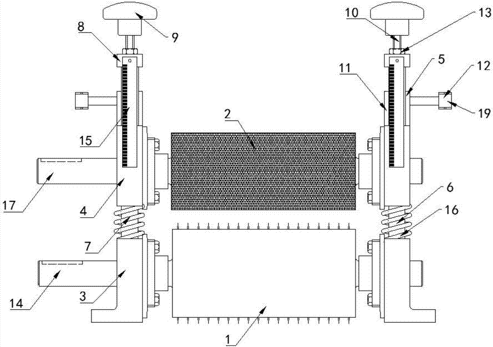
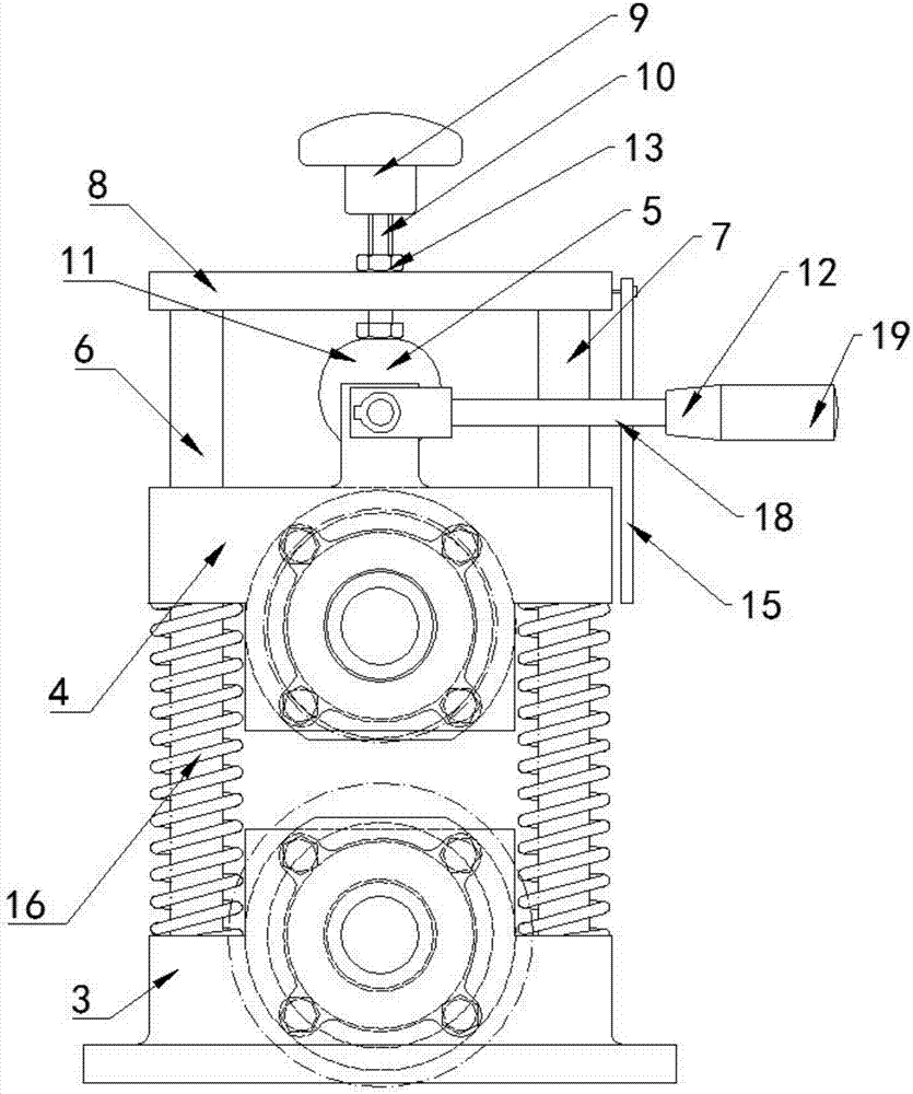
[0033] A new type of puncture machine, which is characterized in that it includes a cold puncture roller 1, a rubber roller 2, a lower bearing seat 3 symmetrically arranged at both ends of the cold puncture roller 1, an upper bearing seat 4 symmetrically arranged at both ends of the rubber roller 2, and a symmetrical arrangement A height adjustment device 5 that drives the upper bearing seat 4 to move in the vertical direction above the upper bearing seat 4;
[0034] A vertical shaft group 6 is symmetrically provided at both ends of the lower bearing seat 3. The vertical shaft group 6 includes two vertical shafts 7 arranged in parallel. Both ends of the upper bearing seat 4 are sleeved on the vertical shaft 7, and the upper bearing seat 4 and The lower bearing seat 3 is connected; a spring 16 for supporting the upper bearing seat 4 is arranged between the upper bearing seat 4 and the lower bearing seat 3, and the spring 16 is sleeved on the vertical shaft 7;
[0035] A top plate 8 ...
Embodiment 2
[0037] This embodiment is further optimized based on embodiment 1. A scale 15 is vertically arranged on one side of the top plate 8 so that the displacement of the rubber roller 2 in the vertical direction can be conveniently observed, so as to accurately control the rubber roller 2 and the cold puncture The gap between the rollers 1 ensures the puncture quality of the present invention.
Embodiment 3
[0039] This embodiment is further optimized based on embodiment 1. A second motor 17 is provided at one end of the upper bearing housing 4 to drive the rubber roller 2 to rotate. When the first motor 14 fails or is damaged, the second motor 17 can be used to drive the rubber The roller 2 rotates so that the present invention can still be used normally.
PUM
 Abstract
Description
Claims
Application Information