
Demand side response control method based on supply and demand side time interval electricity ratio

A demand-side response and demand-response technology, applied in data processing applications, instruments, resources, etc., can solve problems such as shortening the control interval, speeding up the control, and failing to achieve the results of demand-response control, improving tracking capabilities and enhancing tracking effect of ability

Inactive Publication Date: 2017-10-13
SOUTHEAST UNIV
View PDF4 Cites 7 Cited by
  • Summary
  • Abstract
  • Description
  • Claims
  • Application Information

AI Technical Summary

Problems solved by technology

[0004] However, with the vigorous construction of new energy power generation in the country, in consideration of minimizing the abandonment of wind and light, sometimes it is more necessary to consume the electricity generated by new energy power generation than to reduce the load. Therefore, in addition to a single load reduction, The control methods of demand response need to be increased, the control speed needs to be accelerated, and the control interval also needs to be shortened. At present, the two mainstream demand response methods of incentive type and price type cannot achieve the best demand response control results under the single action.

Method used


Image

  • Demand side response control method based on supply and demand side time interval electricity ratio
  • Demand side response control method based on supply and demand side time interval electricity ratio
  • Demand side response control method based on supply and demand side time interval electricity ratio

Examples


Embodiment Construction

[0025] The present invention will be further described in detail below with reference to the drawings and specific embodiments.

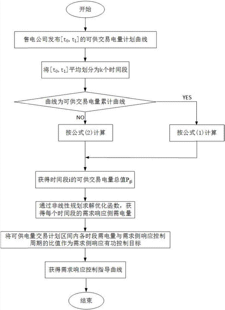
[0026] The control object of the present invention is the power consumption side participating in the demand response, and the demand response amount of the power consumption side is controlled through the node active power prediction curve and the load rate of the curve issued by the electricity sales company. Such as figure 1 As shown, the demand-side response control method based on the ratio of the electricity amount between the supply and demand parties in a period of time in the present invention includes the following steps:

[0027] (1) The time interval of the available electricity trading plan curve issued by the electricity sales company (t 0 ,t 1 ] Averagely divided into k time periods, the length of each time period is marked as T, according to the formula to calculate the total value of available power P of time period i gi , If the provid...


PUM


Abstract

The invention discloses a demand side response control method based on a supply and demand side time interval electricity ratio and belongs to the demand side response control technology field. The method comprises steps that firstly, an available electricity transaction plan interval is divided into multiple time intervals according to a demand side response control period, and available electricity of each time interval is calculated according to an available electricity transaction plan curve; secondly, a smallest variance of ratios of required electricity of each time interval of the available electricity transaction plan interval to available electricity is taken as a target function, for taking regard of constraints that total electricity demand in the available electricity transaction plan interval is basically unchanged and required electricity difference of adjacent time intervals is smaller than controllable electricity in the demand side response control period, an optimization calculation model of required electricity of each time interval is established, and a non-linear plan method is employed to calculate required electricity of each time interval; and lastly, a ratio of required electricity of each time interval of the available electricity transaction plan interval to the demand side response control period is taken as a demand side response active control target, and good interaction between demand side response control and an available electricity transaction plan can be realized.

Description

Technical field [0001] The invention relates to a demand-side response control method based on the ratio of time-division power of the supply and demand parties, belonging to the technical field of new energy power generation and demand-side response control. Background technique [0002] With the continuous progress of society, the power industry is also developing rapidly. The installed power capacity, power consumption and power load are all increasing, but this has also led to the emergence of an energy crisis. The energy crisis has made all sectors of society generally realize the importance of terminal power saving, improving energy utilization, and achieving two-way adjustment of resource supply and demand. At the same time, as the national strategy for the development of smart grids is proposed, Demand Side Management (DSM) also participates in the two-way interaction with the grid in the form of demand response (DR) from the technical feasibility. [0003] According to th...

Claims


Application Information

Patent Timeline
Patent Type & Authority Applications(China)
IPC IPC(8): G06Q10/06G06Q50/06
CPCG06Q10/06315G06Q50/06
Inventor 汤奕徐筝宁佳
Owner SOUTHEAST UNIV
Learn More