

Sliding bearing element
A technology for sliding bearings and supporting components, which is applied in the direction of bearing components, sliding contact bearings, engine components, etc., and can solve the problems of damage, adaptation (slow running-in wear, fatigue, etc.)
Active Publication Date: 2017-10-13
MIBA SINTER AUSTRIA
View PDF16 Cites 3 Cited by
- Summary
- Abstract
- Description
- Claims
- Application Information
AI Technical Summary
Problems solved by technology
At the same time, the high wear resistance of the reinforced coating can lead to the desired adaptation of the bearing surface to the shaft (run-in wear) occurring too slowly or only to an insufficient extent
During prolonged run-in wear phases, irreversible damage in the form of fatigue, cracks and / or fractures can occur due to overloading of the surface coating due to incomplete loading ratios (Traganteil)
Method used
View moreImage
Smart ImageViewing Examples

Examples
example 1
[0140] structure
[0141]
[0142] result
[0143]
[0144] Compared to comparative example 2, an improvement in the load carrying capacity of the plain bearing element 1 is achieved.
example 2
[0146] structure
[0147]
[0148] result
[0149]
[0150]
[0151] It is also shown in this example that, compared to comparative example 3, an improvement in the load-carrying capacity of the plain bearing element 1 is achieved.
example 3
[0153] structure
[0154]
[0155] result
[0156]
[0157] It is shown here that compared to Comparative Example 4, improvements are achieved in both tests.
Login to View More PUM
| Property | Measurement | Unit |
|---|---|---|
| particle size | aaaaa | aaaaa |
| width | aaaaa | aaaaa |
| diameter | aaaaa | aaaaa |
Abstract
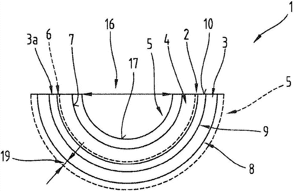
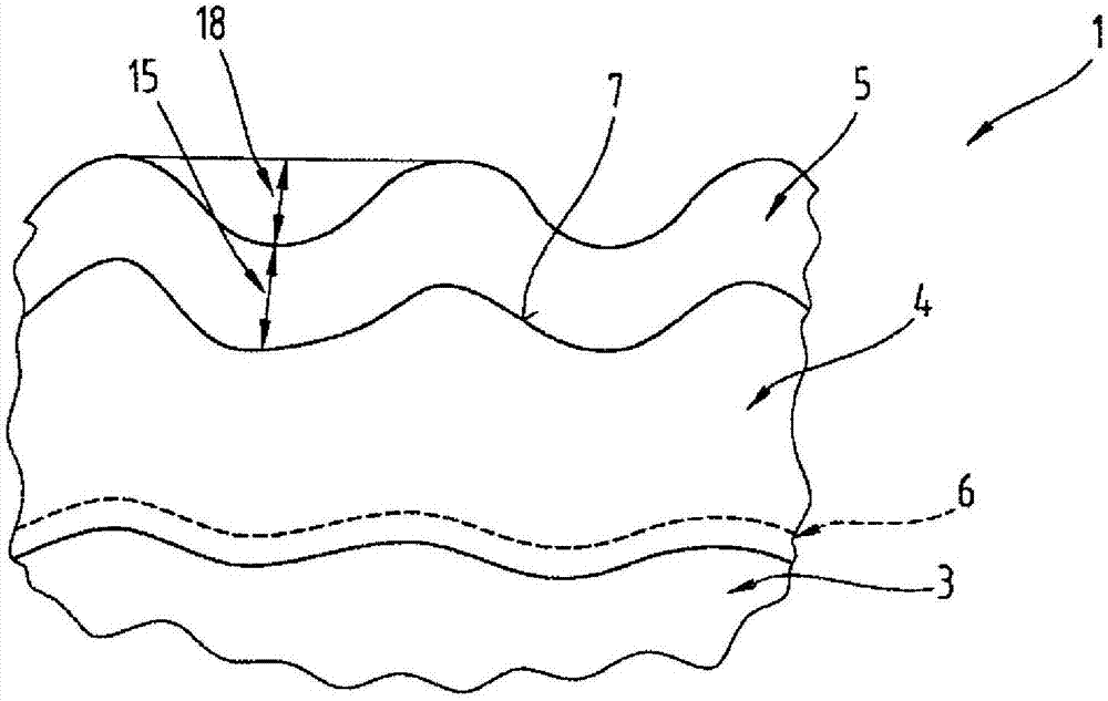
The invention relates to a sliding bearing element (1) with a running layer (4) made of a first tin-based alloy and an additional layer (5) made of an additional tin-based alloy, said alloys containing at least one element of a group comprising Cu, Ni, Ag, Sb, As, Pb, Bi, Te, Tl and / or non-metal particles. The first tin-based alloy has a strength index FI of at least 5 and maximally 25 and the additional tin-based alloy has a strength index (FI) of at least 0.3 and maximally 3. The strength index of the running layer (4) is at least five times the strength index of the additional layer (5), and the strength index FI is defined by the equation, in which C represents at least one of the elements Cu, Ni, Ag; S represents Sb and / or non-metal particles; B represents at least one of the elements Pb, Bi, Te, Tl; and omega represents the total content of each of the tin-based alloy components assigned to the letters C, S, and B.
Description
technical field [0001] The invention relates to a plain bearing element, in particular a radial plain bearing element, comprising in the following order: a bearing element which in particular forms a bearing layer; at least one sliding layer; at least one further layer; and, if necessary At least one bearing metal layer between the support element and the at least one sliding layer, wherein the at least one sliding layer consists of at least one first tin-based alloy and the at least one further layer consists of at least A further tin-based alloy composition, said first tin-based alloy and said further tin-based alloy comprising at least one element selected from the group consisting of: Cu, Ni, Ag, Sb, As , Pb, Bi, Te, Tl, and / or comprising non-metallic particles, the at least one first tin-based alloy and the at least one additional tin-based alloy comprising beta tin grains. Background technique [0002] The use of tin-based alloys as so-called running or sliding layers...
Claims
Login to View More Application Information
Patent Timeline
 Patent Type & AuthorityApplications(China)
IPC IPC(8): F16C33/12F16C17/02
CPCB32B15/01C22C13/02C23C28/023F16C33/124F16C2223/70F16C2204/34C25D3/30F16C33/121F16C33/125F16C17/022F16C2360/22C22C13/00C22C30/00F16C17/02F16C33/127F16C43/02
InventorJ·齐达尔
OwnerMIBA SINTER AUSTRIA