
Carving device applied to furniture parts

A technology for furniture parts and consoles, which is used in engraving, decorative arts, painting tools, etc., can solve the problems of low environmental protection performance, poor stability, low work efficiency, etc., so as to improve work efficiency and work quality, and improve engraving. quality, the effect of enhancing the quality of processing

Active Publication Date: 2017-10-17
彭波
View PDF7 Cites 4 Cited by
  • Summary
  • Abstract
  • Description
  • Claims
  • Application Information

AI Technical Summary

Problems solved by technology

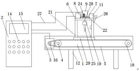
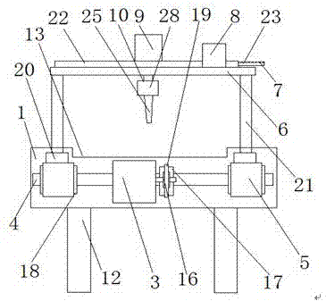
[0003] The purpose of the present invention is to provide a device with reasonable structure design, convenient operation and high work efficiency for the problems of inconvenient operation, poor stability during wood carving process, low work efficiency and low environmental protection performance existing in the existing furniture parts carving device. , Good environmental protection performance, applied to the engraving device of furniture parts

Method used


Image

  • Carving device applied to furniture parts
  • Carving device applied to furniture parts
  • Carving device applied to furniture parts

Examples


Embodiment 1

[0015] as attached figure 1 and 2 Shown: an engraving device applied to furniture parts, including console 1, control cabinet 2, motor one 3, rotating shaft 4, transmission belt 5, bearing plate 6, adjustment plate 7, motor two 8, cylinder 9, engraving The motor 10 and the vacuum motor 11 are characterized in that: the console 1 is set on the bracket 12, and a bearing slot 13 is arranged on the console 1, and the control cabinet 2 is set on one side of the console 1 , and the control cabinet 2 is provided with an operation button 14 and a control panel 15, the motor one 3 is arranged in the console 1, and the motor one 3 is provided with a driving wheel 16, and the rotating shaft 4 is arranged on the In the console 1, a driving wheel 17 and a rotating wheel 18 are arranged on the rotating shaft 4. The transmission belt 5 is arranged between the rotating wheel 18 and the rotating wheel 18, and a fixed plate 20 is arranged on the transmission belt 5. , the bearing plate 6 is a...

Embodiment 2

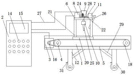
[0020] as attached image 3 Shown: an engraving device applied to furniture parts, including console 1, control cabinet 2, motor one 3, rotating shaft 4, transmission belt 5, bearing plate 6, adjustment plate 7, motor two 8, cylinder 9, engraving The motor 10 and the vacuum motor 11 are characterized in that: the console 1 is set on the bracket 12, and a bearing slot 13 is arranged on the console 1, and the control cabinet 2 is set on one side of the console 1 , and the control cabinet 2 is provided with an operation button 14 and a control panel 15, the motor one 3 is arranged in the console 1, and the motor one 3 is provided with a driving wheel 16, and the rotating shaft 4 is arranged on the In the console 1, a driving wheel 17 and a rotating wheel 18 are arranged on the rotating shaft 4. The transmission belt 5 is arranged between the rotating wheel 18 and the rotating wheel 18, and a fixed plate 20 is arranged on the transmission belt 5. , the bearing plate 6 is arranged...


PUM


Abstract

The invention provides a carving device applied to furniture parts. The carving device applied to the furniture parts comprises an operation platform, a control cabinet, a first motor, a rotating shaft, a conveying belt, a bearing plate, an adjusting plate, a second motor, an air cylinder, a carving motor and a dust collection motor. The carving device applied to the furniture parts is characterized in that the operation platform is arranged on a bracket, the control cabinet is arranged on one side of the operation platform, the first motor is arranged in the operation platform, the rotating shaft is arranged in the operation platform, the conveying belt is arranged between rotating wheels, and the bearing plate is arranged on a fixing plate through a supporting rod. According to the carving device applied to the furniture parts, the first motor and the second motor are arranged as servo motors, the fixing plate can move back and forth on the conveying belt, the adjusting plate can drive the air cylinder to move back and forth, a piston rod of the air cylinder drives the carving motor to move back and forth, carving of different positions is conducted on the furniture parts needing to be carved in the operation platform, the working efficiency and working quality of furniture part carving are improved, and the machining quality of furniture is also enhanced.

Description

technical field [0001] The invention relates to the technical field of furniture processing, in particular to an engraving device applied to furniture parts. Background technique [0002] The engraving machine plays a very important role in the beautiful engravings that appear on some furniture in life. However, the engraving machines that appear on the market currently have relatively single functions, low automation, and many manual operations. If the speed is too slow, it will affect the production efficiency. During the engraving process, a lot of dust and waste will be generated, which will pose a threat to the health of the operator. Moreover, when the knife head and the wood are engraved, there will be a large amount of friction. Noise, which brings a certain amount of noise pollution, does not meet the needs of production. For example, the patent with the application number 201620729274.9 discloses a wood carving device, which solves the problem of generating more s...

Claims


Application Information

Patent Timeline
Patent Type & Authority Applications(China)
IPC IPC(8): B44B3/00B44B3/06
CPCB44B3/009B44B3/06B44B2700/02B44B2700/12
Inventor 彭波夏华
Owner 彭波
Learn More