
Intelligent quenching machine tool and control method for disk parts

A technology of disk parts and quenching machine tools, which is applied in the field of mechanical manufacturing and processing, can solve the problems that the clamping force of parts is difficult to effectively control, limit, and easily cause slippage, so as to reduce the difficulty of fluctuation and control, realize automatic detection, increase The effect of adjusting the space

Active Publication Date: 2018-08-24
ANHUI POLYTECHNIC UNIV
View PDF6 Cites 0 Cited by
  • Summary
  • Abstract
  • Description
  • Claims
  • Application Information

AI Technical Summary

Problems solved by technology

[0003] The bed frames of traditional quenching machine tools are mostly fixed, and do not have small-scale adjustable functions. It is difficult to adapt to different quenching process requirements, which limits the adjustment space for the relative position between parts and quenching sensors; The rollers on the frame support the parts, and the positional relationship between the rollers is set in advance. This kind of roller support method is easy to cause slippage during the rotating quenching process of parts, especially large heavy-duty parts, and there is a certain degree of safety. Hidden dangers, and it is mainly suitable for parts of fixed size, but for batch quenching of parts of different sizes, it is difficult to automatically adjust the function of clamping size, and it is difficult to effectively control the clamping force applied to parts, and the clamping force is too high If the clamping force is too large, it will easily cause surface and internal damage to the parts
[0004] Traditional quenching machine tools limit the quenching heat treatment of a large number of components with different structural parameters, which reduces the efficiency, reliability and quality of quenching, and it is difficult to realize the intellectualization of the quenching process

Method used


Image

  • Intelligent quenching machine tool and control method for disk parts
  • Intelligent quenching machine tool and control method for disk parts
  • Intelligent quenching machine tool and control method for disk parts

Examples


Embodiment Construction

[0039] The following will clearly and completely describe the technical solutions in the embodiments of the present invention with reference to the accompanying drawings in the embodiments of the present invention. Obviously, the described embodiments are only some, not all, embodiments of the present invention. Based on the embodiments of the present invention, all other embodiments obtained by persons of ordinary skill in the art without making creative efforts belong to the protection scope of the present invention.

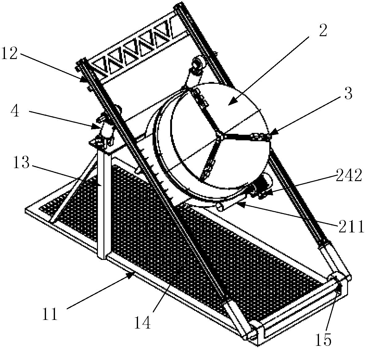
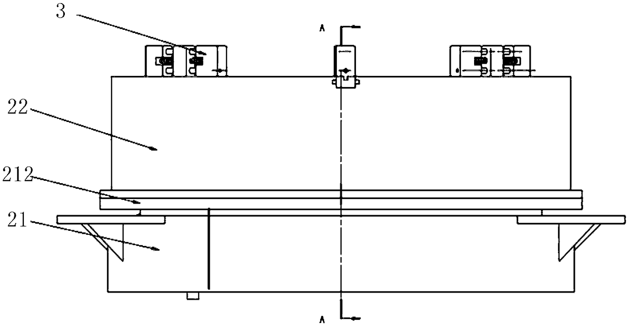
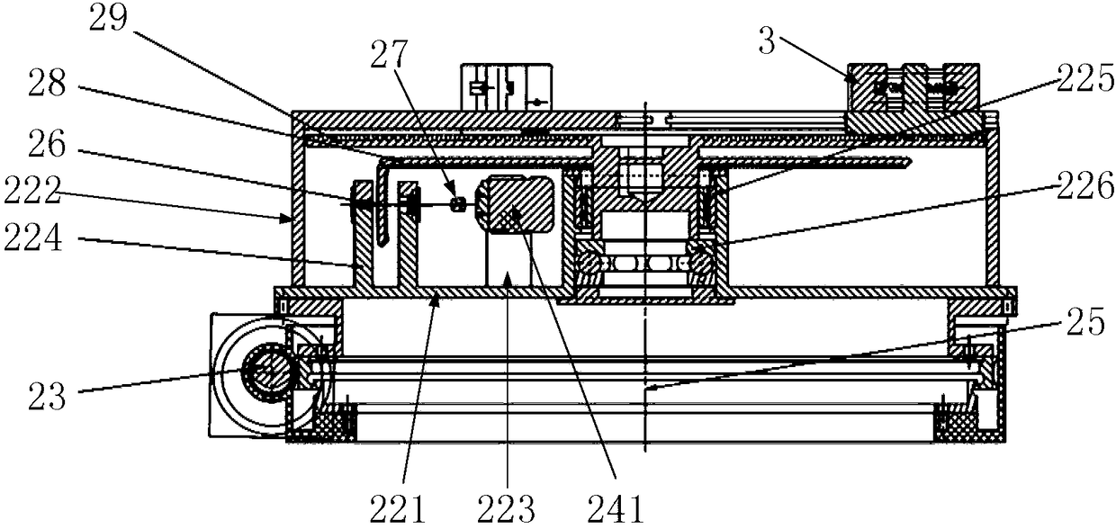
[0040] Such as figure 1 , figure 2 , image 3 , Figure 4 , Figure 5 , Figure 6 As shown, it is an intelligent quenching machine tool for disc parts,

[0041] It includes an adjustable frame composed of a frame base 11 and an inclined support frame 12, and a quenching workbench composed of a turntable 2 and an intelligent claw 3 arranged on the turntable 2;

[0042] The frame base 11 and the inclined support frame 12 are connected by constraints that ...


PUM


Abstract

The invention discloses an intelligent quenching machining tool for disc parts. The intelligent quenching machining tool for the disc parts comprises an adjustable rack and a quenching workbench; the adjustable rack comprises a rack base and an inclined bearing frame; and the quenching workbench comprises a rotary table and intelligent clamping claws. At the same time, the invention discloses a control method. The intelligent quenching machining tool for the disc parts and the control method can achieve adjustment of the angle between the rack base and the inclined bearing frame, adapt to different quenching process requirements, and increase the adjustment space between the parts and a quenching sensor; as for different quenching workpieces, adjustment of the clamping size of the intelligent clamping claws can be achieved; at the same time, the placement positions of the parts can be effectively detected, so that the parts are put in the center of the rotary table; and automatic detection of clamping in place is achieved, collision between the machining tool and the surfaces of the parts is avoided, buffering mechanisms and sensors for sensing the pressure are arranged inside the intelligent clamping claws and can effectively control the clamping force of the parts, and damage to the surfaces and the interiors of the parts is avoided.

Description

technical field [0001] The invention relates to an intelligent quenching machine tool and a control method for disk parts, belonging to the technical field of mechanical manufacturing and processing. Background technique [0002] Quenching is an important heat treatment process, and disc parts (such as gears) have high requirements and large demand for quenching equipment due to their special structure and wide application. [0003] The bed frames of traditional quenching machine tools are mostly fixed, and do not have small-scale adjustable functions. It is difficult to adapt to different quenching process requirements, which limits the adjustment space for the relative position between parts and quenching sensors; The rollers on the frame support the parts, and the positional relationship between the rollers is set in advance. This kind of roller support method is easy to cause slippage during the rotating quenching process of parts, especially large heavy-duty parts, and ...

Claims


Application Information

Patent Timeline
Patent Type & Authority Patents(China)
IPC IPC(8): C21D11/00C21D9/32C21D1/62
CPCC21D1/62C21D9/32C21D11/00
Inventor 刘玉飞张俊强张席赵敏于华许德章
Owner ANHUI POLYTECHNIC UNIV
Learn More