Device for shin bone fractured end force line correction

A technology of end force and tibia, which is applied in the direction of diagnosis, application, medical science, etc., can solve problems affecting the recovery of patients' limb functions, errors in judging force lines, and operation failures, and achieves improved operation success rates, low production costs, and fixed good effect

Pending Publication Date: 2017-10-20
宜宾市第一人民医院
View PDF5 Cites 0 Cited by
  • Summary
  • Abstract
  • Description
  • Claims
  • Application Information

AI Technical Summary

Problems solved by technology

In order to solve the problem of infection and bone defect, a method of thorough debridement combined with external frame bone transfer is specially used. However, after removing the inactivated bone, the force line of the broken end of the bone needs to be adjusted. Only when the force line is good can the bone be lengthened. The alignment of the alignment is accurate and correct, avoiding the situation that the broken bone cannot be fixed and re-displaced, which will lead to the failure of the operation; at present, the traditional way of correcting the alignment is that the operator judges the specific situation of the broken bone based on experience during the operation, combined with Repeated fluoroscopy data of the C-arm is used to align the force line of the broken bone of the patient. This method has a large error, and errors in judging the force line are very likely to occur, resulting in the problem that the broken bone cannot be fixed and shifted again. Secondly, postoperative recovery Poor, seriously affecting the recovery of the patient's limb function

Method used


Image

  • Device for shin bone fractured end force line correction
  • Device for shin bone fractured end force line correction
  • Device for shin bone fractured end force line correction

Examples


Embodiment Construction

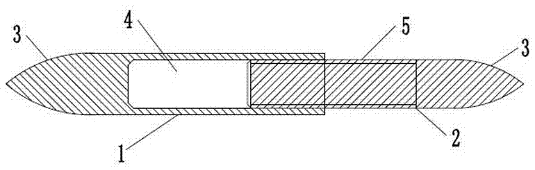
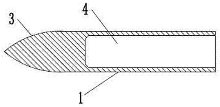
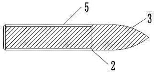
[0011] The present invention will be further described below in conjunction with the examples, but the present invention is not limited in any way, and any transformation or substitution made based on the teaching of the present invention belongs to the protection scope of the present invention. According to attached Figure 1~2 Shown 1. A device for rectifying the force line of the broken end of the tibia, which is characterized in that: it includes a sleeve rod 1 and a support rod 2, one end of the sleeve rod 1 is provided with a tapered end 3, and the other end is provided with a mounting hole 4. An internal thread is provided in the installation hole 4, an external thread 5 is provided at one end of the support rod 2, and a tapered end 3 is provided at the other end. The sleeve rod 1 and the support rod 2 are threadedly connected so that the support rod 2 Screw it into the mounting hole 4 of the sleeve rod 1.

[0012] The diameter of the sleeve rod 1 is not less than 1 cm...


PUM


Abstract

The invention discloses a device for shin bone fractured end force line correction. The device comprises a sleeve rod and a support rod, wherein a conical end part is arranged at one end of the sleeve rod; an installing hole is formed in the other end of the sleeve rod; internal screw threads are arranged in the installing hole; external screw threads are arranged at one end of the support rod; a conical end part is arranged at the other end of the support rod; and the sleeve rod and the support rod are matched and connected through screw threads, so that the support rod is screwed into the installing hole of the sleeve rod. The device has the advantages that the conical end of the sleeve rod is inserted into the far bone fractured end; the conical end of the support rod is inserted into the near bone fractured end; the length of the sleeve rod and the support rod is properly regulated by rotating the sleeve rod and the support rod; a force line device is lengthened; the front, back and lateral side displacement of the bone fractured end is corrected; auxiliary fixation is performed; the reset is maintained; and the occurrence of the condition that the bone fractured end cannot be fixed or displaced again due to single naked eye or manual force line judgment errors is avoided. The device has the advantages that the structure is simple; the manufacturing cost is low; the use is convenient; the correction and fixation effects are good; and the operation successful rate and the postoperative limb function recovery effect are improved.

Description

technical field [0001] The invention belongs to the technical field of medical devices, and in particular relates to a device for correcting tibial stump force lines which is easy to use and has good correction and fixation effects. Background technique [0002] In the postoperative recovery of orthopedic tibial surgery, subject to the patient's own and external environmental factors, patients with chronic osteomyelitis, infected nonunion and post-traumatic bone infection often do not heal, and repeated debridement of the trauma is required , resulting in bone defects that often follow debridement. Due to the difficulty and long cycle of treatment of infection and bone defect, it brings great physical and mental pain to patients, which is a major problem for orthopedic surgeons. In order to solve the problem of infection and bone defect, a method of thorough debridement combined with external frame bone transfer is specially used. However, after removing the inactivated b...

Claims


Application Information

Patent Timeline
Patent Type & Authority Applications(China)
IPC IPC(8): A61B90/00A61B17/56
CPCA61B17/56A61B90/00A61B2017/564
Inventor 齐保闯徐显春
Owner 宜宾市第一人民医院
Why Eureka
Try Eureka