Steel cord wire-drawing die

A technology for drawing dies and steel cords, applied in the direction of drawing dies, etc., can solve the problems of large drawing force, large compression ratio, low productivity, etc., and achieve the effects of reducing drawing force, increasing compression ratio, and fast setting.

Inactive Publication Date: 2017-10-20
杨飞
View PDF7 Cites 4 Cited by
  • Summary
  • Abstract
  • Description
  • Claims
  • Application Information

AI Technical Summary

Problems solved by technology

The currently used steel cord wire drawing die has a large compression angle in the working area, a short height in the working area, and a large height in the sizing area; a large compression angle in the working area and a short height make the compression ratio large and the drawing force low It will increase, the height of the sizing area is high, the contact area between the wire and the sizing area is large, and the friction force is large. When the wire drawing speed is increased, the wire is easy to break, resulting in low productivity, and the large drawing force leads to high energy consumption.

Method used


Image

  • Steel cord wire-drawing die

Examples


Embodiment Construction

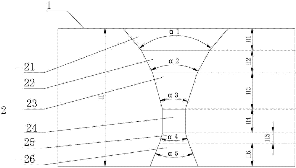
[0017] Such as figure 1 as shown, figure 1 It is a structural schematic diagram of a steel cord wire drawing die proposed by the present invention.

[0018] refer to figure 1 , the present invention proposes a steel cord wire drawing die, including a die body 1, the die body 1 has a wire drawing hole 2, and the hole structure of the wire drawing hole 2 is divided into an entrance area 21, a lubrication area 22, and a working area 23 from top to bottom. , the sizing area 24, the decompression area 25, the exit area 26, and the arc transition between the entrance area 21, the lubrication area 22, the working area 23, the sizing area 24, the decompression area 25, and the exit area 26, and the entrance area 21 , the lubricating area 22 and the working area 23 are inverted cones, the decompression area 25 and the outlet area 26 are positive cones, the sizing area 24 is cylindrical, the cone angle of the inlet area 21 is ɑ1, and the cone angle of the lubricating area 22 is ɑ2, t...


PUM


Abstract

The invention provides a steel cord wire-drawing die. The steel cord wire-drawing die comprises a die body; a wire drawing hole is formed in the die body; the conical angle of an inlet zone is alpha 1; the conical angle of a lubrication zone is alpha 2; the conical angle of a sizing zone is alpha 3; the conical angle of a decompression zone is alpha 4; the conical angle of an outlet zone is alpha 5; and alpha 1 is greater than alpha 2; alpha 2 is greater than alpha 5; alpha 5 is greater than alpha 3; alpha 3 is equal to alpha 4; the height of the die body is H; the height of the inlet zone is H1; the height of the lubrication zone is H2; the height of a working zone is H3; the height of the sizing zone is H4; the height of the decompression zone is H5; the height of the outlet zone is H6; H3 is greater than H4; H4 is greater than H6; H6 is greater than H2; H2 is equal to H1; and H1 is greater than H5. According to the steel cord wire-drawing die, during wire drawing, stability of a metal wire is increased; the metal wire can transit smoothly, so that the metal wire is not easily broken; thickness of the product is uniform; plastic deformation and elastic deformation of the metal wire are reduced; the conical angle of the working zone is equal to that of the decompression zone, so that reduction and uniform distribution of the friction force are favorably realized during a drawing process of the metal wire; abrasion of a die hole of the wire-drawing die is lowered; heat generated by friction of the metal wire and the die can be dissipated in time; and the service life of the die is prolonged.

Description

technical field [0001] The invention relates to the technical field of wire drawing dies, in particular to a steel cord wire drawing die. Background technique [0002] Steel cord is a fine-gauge steel wire strand or rope made of high-quality high-carbon steel with a brass-plated surface and a special purpose. Mainly used for car tires, light truck tires, heavy truck tires, construction machinery tires and aircraft tires and other rubber products skeleton materials. The radial tire made of steel cord as a reinforcing material has the advantages of long service life, fast driving speed, puncture resistance, good elasticity, safety and comfort, and fuel saving. The currently used steel cord wire drawing die has a large compression angle in the working area, a short height in the working area, and a large height in the sizing area; a large compression angle in the working area and a short height make the compression ratio large and the drawing force low It will increase, the h...

Claims


Application Information

Patent Timeline
Patent Type & Authority Applications(China)
IPC IPC(8): B21C3/02B21C9/00
CPCB21C3/02B21C9/00
Inventor 杨飞
Owner 杨飞
Why Eureka
Try Eureka