
Kinetic energy input device of multi-shaft numerical control machine tool

A technology of CNC machine tools and input devices, applied in positioning devices, metal processing machinery parts, clamping, etc., can solve the problems of uncontrollable tool movement, limited processing area, inability to combine turning and planing, etc.

Active Publication Date: 2017-10-20
上海丰荷智能科技有限公司
View PDF5 Cites 1 Cited by
  • Summary
  • Abstract
  • Description
  • Claims
  • Application Information

AI Technical Summary

Problems solved by technology

[0003] The machine tools in the prior art have mature technology and high processing precision, and can realize functions such as turning, milling, boring, and drilling, but cannot effectively combine turning and planing; the tool clamping mechanism of the three-axis machine tool in the prior art It is usually fixed and cannot control the movement of the tool along the axis, thus limiting the processing area

Method used


Image

  • Kinetic energy input device of multi-shaft numerical control machine tool
  • Kinetic energy input device of multi-shaft numerical control machine tool
  • Kinetic energy input device of multi-shaft numerical control machine tool

Examples


Embodiment Construction

[0062] The technical solutions in the embodiments of the present invention will be clearly and completely described below in conjunction with the accompanying drawings in the embodiments of the present invention. Obviously, the described embodiments are only some, not all, embodiments of the present invention. Based on the embodiments of the present invention, all other embodiments obtained by persons of ordinary skill in the art without making creative efforts belong to the protection scope of the present invention.

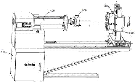
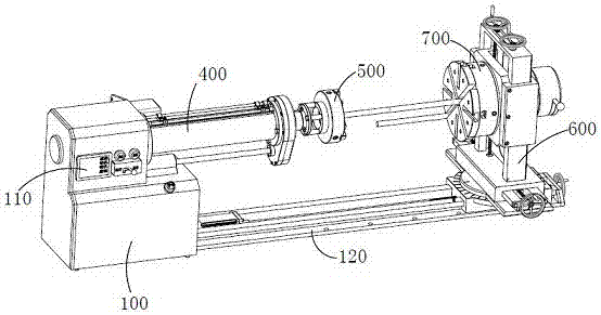
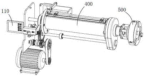
[0063] Such as figure 1 , 2 , 3, a high-precision multi-axis machine tool, which includes a frame 100, a controller 110 mounted on the frame 100, a dual power mechanism 400 mounted on one end of the frame 100, a motion mechanism mounted on the other end of the frame 100 The bracket 600 , the tool clamping mechanism 500 installed on the output end of the dual power mechanism 400 , and the workpiece clamping mechanism 700 installed on the moving bracket 600 .

...


PUM


Abstract

The invention discloses a kinetic energy input device of a multi-shaft numerical control machine tool. The kinetic energy input device comprises a first main shaft, a locking mechanism connected with the first machine shaft and a shifting mechanism connected with the locking mechanism; the drive end of the first main shaft is connected with the locking mechanism, the locking mechanism comprises a second gear, a movable locking disc and a fixed locking disc, wherein the second gear is connected to the first main shaft in a sleeved manner, the movable locking disc is fixedly connected to the first main shaft in a sleeved manner, and the fixed locking disc is connected to the first main shaft in a sleeved manner and fixed to a rack; the first main shaft is provided with an axial key groove formed in the axis direction of the first main shaft, and the second gear is matched with the axial key groove through a key and is movably connected outside the first main shaft in a sleeved manner; the movable locking disc is provided with a locking protrusion, the fixed locking disc is provided with a locking groove matched with the locking protrusion, and the movable locking disc is provided with an annular shifting groove, wherein the annular shifting groove and the movable locking disc are concentrically arranged; and a second spring connected to the first main shaft in a sleeved manner is installed between the movable locking disc and the second gear.

Description

[0001] The present invention is a divisional application of an invention patent with the application date of May 25, 2016, the application number: 2016103542006, and the invention title of "Workpiece Clamping Mechanism with Orientation Around Z-axis, Fixed Angle, and Fixed Speed ​​Deflection". technical field [0002] The invention relates to the technical field of mechanical processing, in particular to a multi-axis machine tool capable of realizing functions such as turning, milling, boring, drilling and planing. Background technique [0003] The machine tools in the prior art have mature technology and high processing precision, and can realize functions such as turning, milling, boring, and drilling, but cannot effectively combine turning and planing; the tool clamping mechanism of the three-axis machine tool in the prior art It is usually fixed and cannot control the movement of the tool along the axis, thus limiting the processing area. Contents of the invention [0...

Claims


Application Information

Patent Timeline
Patent Type & Authority Applications(China)
IPC IPC(8): B23B31/10B23Q3/00
CPCB23B31/10B23Q3/00
Inventor 张玲玲
Owner 上海丰荷智能科技有限公司
Learn More