
Universal spindle box device for machine tools

A spindle box and machine tool technology, which is applied in the direction of metal processing machinery parts, metal processing equipment, manufacturing tools, etc., can solve the problems of reduced processing area, reduced processing accuracy of workpieces, and processing of large workpieces, so as to reduce the length and width, increase the Processing area, effect of flexible processing

Active Publication Date: 2018-03-16
DN SOLUTIONS CO LTD
View PDF3 Cites 0 Cited by
  • Summary
  • Abstract
  • Description
  • Claims
  • Application Information

AI Technical Summary

Problems solved by technology

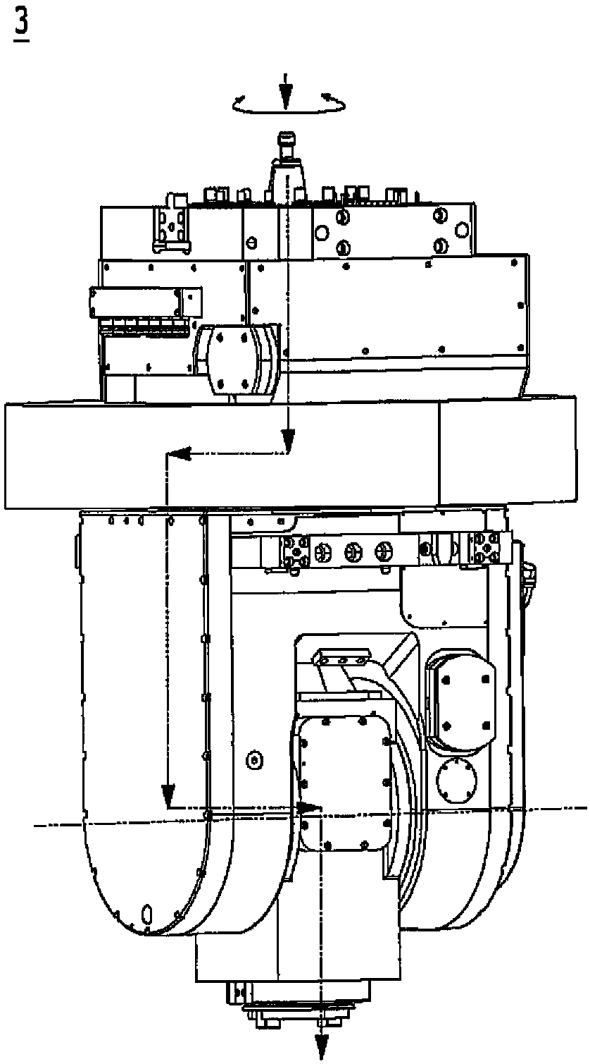
[0010] In this way, the existing universal headstock device 3 needs to install various units on the universal headstock device in order to rotate the headstock part with the rotational power of the slider spindle. The width increases, and there is a problem that the miniaturization and weight reduction of the universal headstock device cannot be realized, and the processing area is reduced.
[0011] In addition, the existing universal headstock device is installed at the end of the main shaft of the slider. The length and width of the universal headstock device itself are relatively large, and the weight is heavy. small problem
[0012] In addition, the existing universal headstock device realizes the machining of the workpiece in a state where the length and width are relatively increased, thereby increasing the generation amount of residual vibration, and thus there is a problem that the machining accuracy of the workpiece is significantly lowered.
[0013] In addition, the existing universal headstock device cannot be miniaturized, so there is a problem that the processing area is reduced and large workpieces that require a relatively large processing area cannot be processed
[0014] In addition, in the conventional universal headstock device, when the headstock part is tilted, the headstock part cannot be tilted uniformly, or the headstock part has an inversion phenomenon in which the headstock part rotates in the opposite direction, and there is a problem that the machining accuracy of the workpiece is reduced.

Method used


Image

  • Universal spindle box device for machine tools
  • Universal spindle box device for machine tools
  • Universal spindle box device for machine tools

Examples


Embodiment Construction

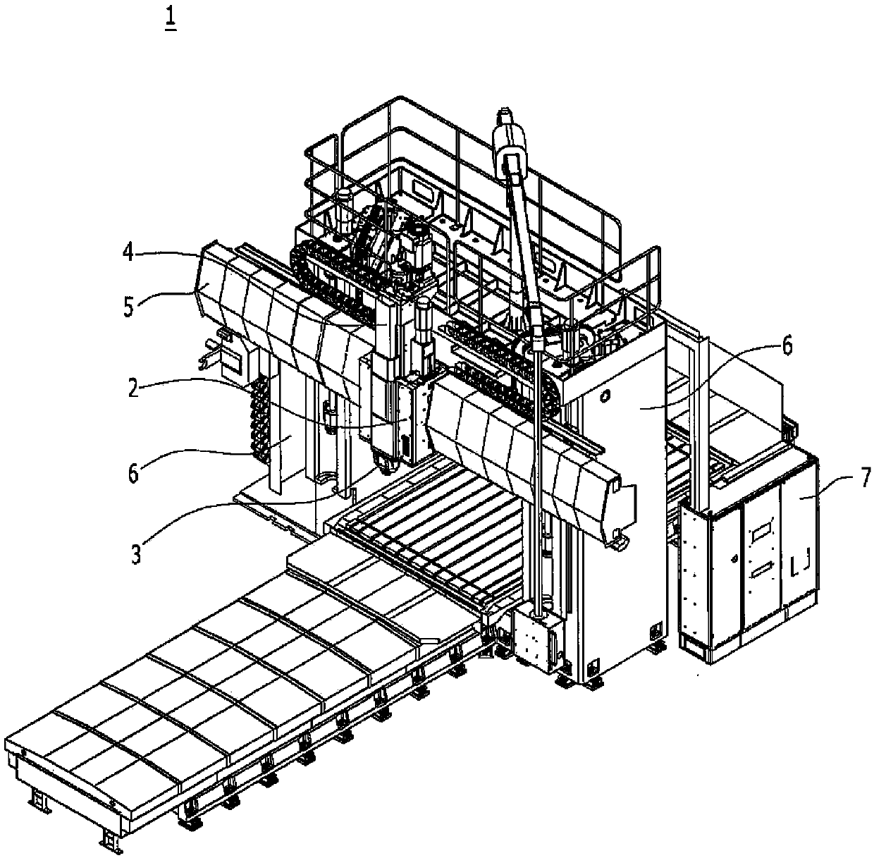
[0107] The preferred embodiments of the present invention will be described in detail with reference to the drawings. First, by attaching reference signs to the structural elements of the respective drawings, the same structural elements have the same reference signs.

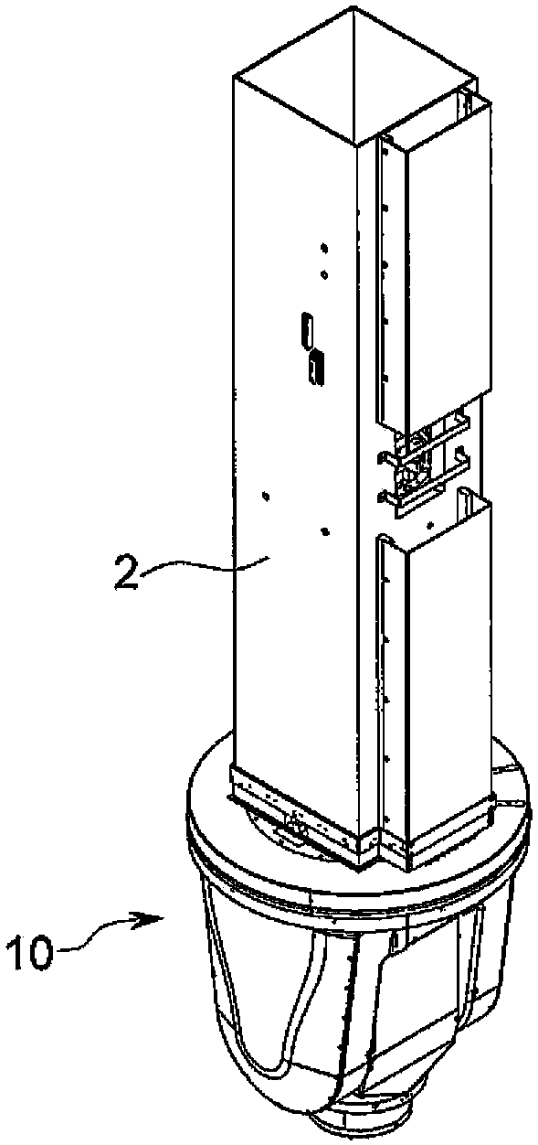
[0108] image 3 A perspective view showing the state in which the universal headstock device 10 for machine tools according to the present invention is mounted on the slider spindle 2, Figure 4 A cross-sectional view of a universal headstock device 10 for a machine tool according to an embodiment of the present invention is shown.

[0109] Reference image 3 and Figure 4 The universal headstock device 10 for machine tools according to the present invention will be described. The universal headstock device 10 for a machine tool according to a preferred embodiment of the present invention may include a rotating main body part 100, an inclined main body part 200, and a headstock part 300.

[0110] In a machine tool, e...


PUM


Abstract

The invention relates to an all-powerful spindle box device used for a machine tool, and specifically relates to an all-powerful spindle box device used for a machine tool. The device uses a rotation which receives rotary power of a sliding block spindle to make a rotation main body portion rotate, uses an additional working unit which is used as a power source to make a spindle box part rotate, and uses an inclination unit to make vibration minimum when the spindle box part inclines. The all-powerful spindle box device can realize miniaturization and light weight, reduces backlash generated when the rotation rotates, so as to reduce reduction of flexible rigidity and residual vibration, and increases processing regions and processing precision.

Description

Technical field [0001] The present invention relates to a universal headstock device, in particular, to a rotating unit that receives the rotational power of a slider spindle to rotate a rotating main body, and a working unit as another power source to rotate the headstock, using The tilting unit minimizes vibration when the headstock part is tilted, and can reduce the size and weight of the universal headstock device, and can reduce the backlash generated when the rotating part rotates, thereby reducing the reduction in bending rigidity and residual vibration A universal headstock device for machine tools that can increase the processing area and processing accuracy. Background technique [0002] Various types of machine tools, including turning machining centers, machining centers, gantry machining centers, Swiss-style lathes, EDM machines, horizontal CNC boring machines, CNC lathes, etc., are used in different industrial sites according to the purpose of the corresponding oper...

Claims


Application Information

Patent Timeline
Patent Type & Authority Patents(China)
IPC IPC(8): B23B19/00
CPCB23Q1/70
Inventor 姜晓锡具熙春
Owner DN SOLUTIONS CO LTD
Learn More