
Solder composition and electronic board

A composition, solder technology, applied in welding/cutting media/materials, welding media, welding equipment, etc., that can solve problems such as pores without reducing large diameters

Active Publication Date: 2017-10-20
TAMURA KK
View PDF11 Cites 8 Cited by
  • Summary
  • Abstract
  • Description
  • Claims
  • Application Information

AI Technical Summary

Problems solved by technology

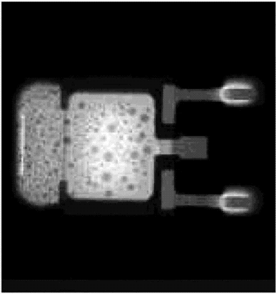
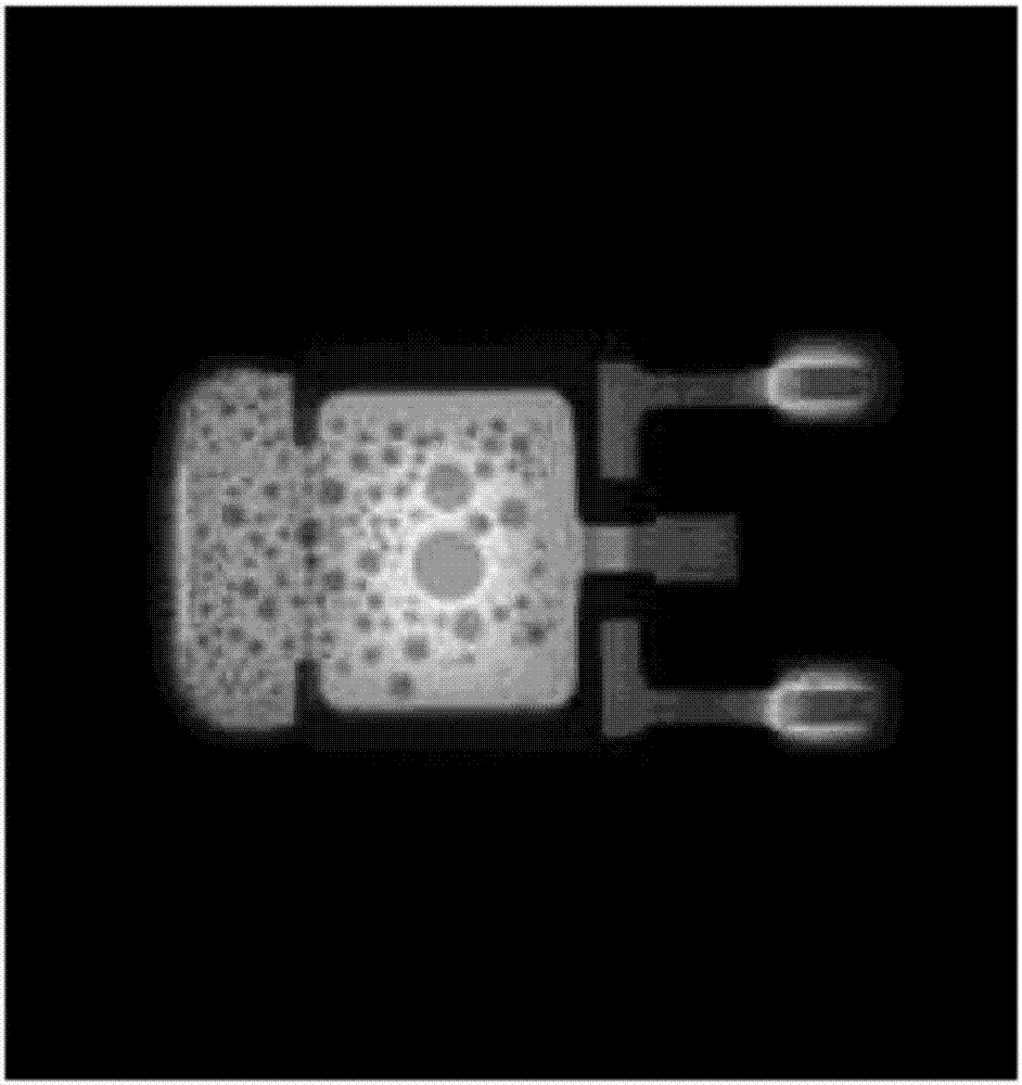
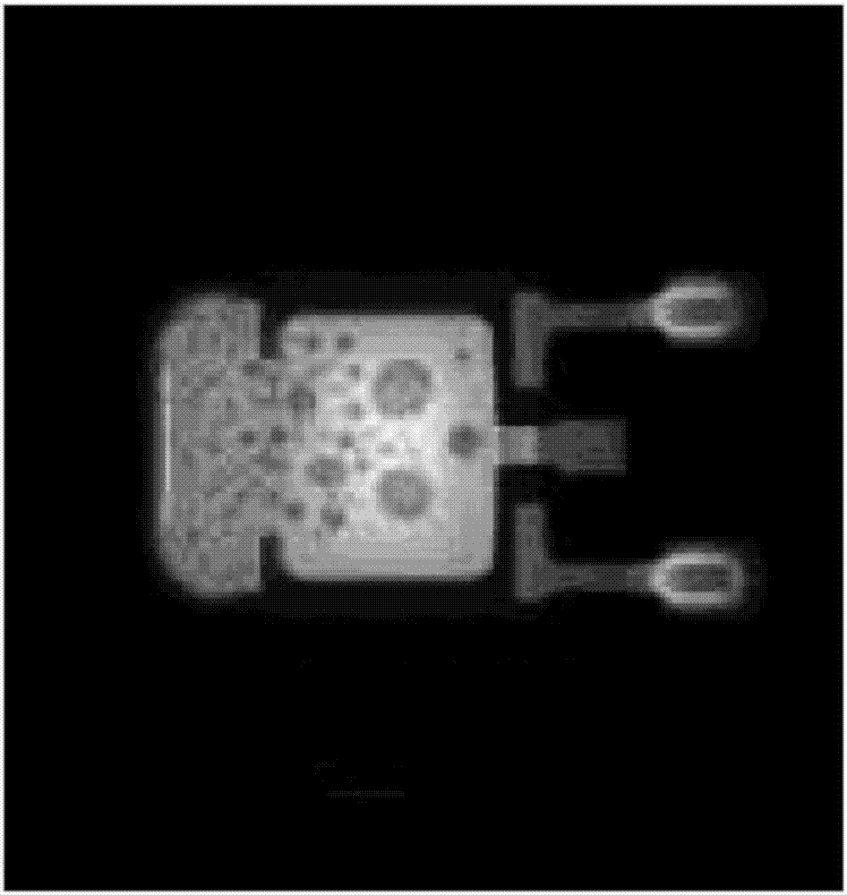
However, it is known that even if such a solvent with a high boiling point and high viscosity is used, there is no effect of reducing large-diameter pores in electronic components such as power transistors with large electrode terminal areas.

Method used


Image

  • Solder composition and electronic board
  • Solder composition and electronic board
  • Solder composition and electronic board

Examples


Embodiment 1

[0098] 42% by mass of rosin resin, 2.1% by mass of activator A, 2% by mass of activator B, 13% by mass of solvent A, 8% by mass of solvent B, 20.9 parts by mass of solvent E, and 12% by mass of thixotropic agent were put into the container, and used A planetary mixer was used to obtain a flux composition.

[0099] Then, 10.2% by mass of the obtained flux composition and 89.8% by mass of the solder powder (100% by mass in total) were put into a container and mixed using a planetary mixer to prepare a solder composition.

Embodiment 2~4

[0101] A solder composition was obtained in the same manner as in Example 1 except that various materials were blended according to the composition shown in Table 1.


PUM


Abstract

A solder composition of the invention includes: a flux composition containing a component (A) in a form of a rosin-based resin, a component (B) in a form of an activator, a component (C) in a form of a solvent and a component (D) in a form of a thixotropic agent; and a component (E) in a form of a solder powder. The component (C) in a form of the solvent contains a component (C1) in a form of a isobornyl cyclohexanol and a component (C2) in a form of a solvent whose viscosity at 20 degrees C. is 10 mPa s or less and whose boiling point ranges from 220 degrees C. to 245 degrees C.

Description

technical field [0001] The present invention relates to a solder composition and an electronic substrate. Background technique [0002] The solder composition is a paste-like mixture obtained by kneading a flux composition (rosin-based resin, activator, solvent, etc.) with solder powder (for example, Document 1: Japanese Patent No. 5756067). In this solder composition, not only solderability such as solder meltability and property that solder can easily wet and spread (solder wet and spread), but also void suppression, printability, and the like are required. [0003] On the other hand, due to the diversification of functions of electronic devices, large electronic components have been mounted on electronic substrates. In addition, among large electronic components, there are electronic components having a large electrode terminal area (for example, power transistors). In such an electronic component, since the printed area of ​​the solder composition is large, there is a ...

Claims


Application Information

Patent Timeline
Patent Type & Authority Applications(China)
IPC IPC(8): B23K35/36
CPCB23K35/36
Inventor 市川大悟出水亮岩渕充山下宣宏福田谦太奥村聪史田岛信男
Owner TAMURA KK
Learn More