Supercharge Your Innovation With Domain-Expert AI Agents!

Welding robot driven by lifting motor

A welding robot, lifting motor technology, applied in welding equipment, auxiliary welding equipment, welding/cutting auxiliary equipment, etc., can solve the problems of low overall efficiency, difficult manufacturing, strict assembly requirements, etc., to reduce human labor and improve labor efficiency. , the effect of reducing frictional resistance

Active Publication Date: 2017-10-20
LIUZHOU FUNENG ROBOT DEV CO LTD
View PDF5 Cites 0 Cited by
  • Summary
  • Abstract
  • Description
  • Claims
  • Application Information

AI Technical Summary

Problems solved by technology

There are two types of welding manipulators: mechanical and hydraulic. At present, most of the welding manipulators are hydraulically driven. Since the hydraulic drive uses hydraulic oil as the medium for power transmission, there are the following problems: the starting performance is poor, and it is easy to be damaged due to the wear of internal components. Leakage occurs, and the leaked hydraulic oil will pollute the environment. The hydraulic oil is greatly affected by temperature, the overall efficiency is low, and sometimes there is noise and vibration
Hydraulic components require high processing precision, strict assembly requirements, and difficult manufacturing. Maintenance requires high technology and is difficult during use.
The mechanical welding robot arm of the mechanic uses mechanical transmission parts to realize the welding action, which has the advantages of sturdiness and durability, but the traditional single-degree-of-freedom mechanical welding robot arm cannot complete complex actions, and its application range is very limited

Method used


Image

  • Welding robot driven by lifting motor
  • Welding robot driven by lifting motor
  • Welding robot driven by lifting motor

Examples


Embodiment Construction

[0027] The present invention will be further described in detail below in conjunction with the accompanying drawings, so that those skilled in the art can implement it with reference to the description.

[0028] In the description of the present invention, it should be noted that, unless otherwise specified and limited, the terms "installation", "connection", and "setting" should be understood in a broad sense, for example, it can be fixed connection, setting, or Removably attached, set, or integrally attached, set. Those of ordinary skill in the art can understand the specific meanings of the above terms in the present invention in specific situations. The terms "landscape", "portrait", "top", "bottom", "front", "rear", "left", "right", "vertical", "horizontal", "top", "bottom", The orientation or positional relationship indicated by "inner", "outer", etc. is based on the orientation or positional relationship shown in the drawings, which is only for the convenience of descr...


PUM


Abstract

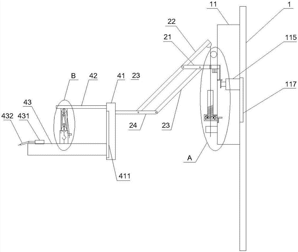
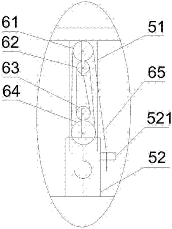
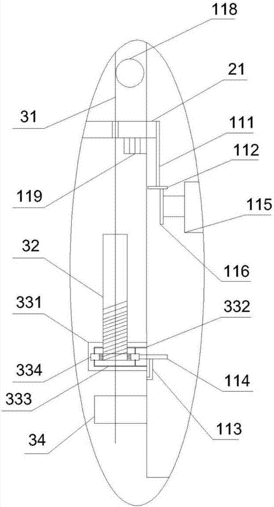
The invention discloses a welding robot driven by a lifting motor. The welding robot driven by the lifting motor comprises a stand column, a rocker arm, a pulling device, a bearing platform and a sleeve and pulley assembly, wherein the rocker arm comprises a first rod body, a second rod body, a third rod body and a fourth rod body, and the first rod body, the second rod body, the third rod body and the fourth rod body are arranged on the same vertical plane; the pulling device comprises a pulling rope, a positioning cylinder, a limiting mechanism and a first locking frame; and the bearing platform comprises a connecting column which is vertically arranged, a hanging frame which is horizontally arranged on the upper portion of one side of the connecting column, and a workbench which is arranged on the lower portion of one side of the connecting column, a fixed base is arranged on the workbench, and a welding gun is mounted on the fixed base. According to the welding robot driven by the lifting motor, through the design of the rocker arm, swing in the horizontal direction and in the vertical direction can be achieved; through the design of the lifting motor, power is selectively provided for horizontal rotation and vertical rotation; through the design of a pulley, fine adjustment of the height of the workbench is achieved, and a multi-station rack can be welded; and the welding robot driven by the lifting motor has the advantages of high welding efficiency, low manufacturing cost and flexible welding stations.

Description

technical field [0001] The invention relates to the field of welding technology. More specifically, the present invention relates to a lifting motor-driven welding robot. Background technique [0002] During the processing of the rack assembly line, it is usually necessary to weld the processed rack, and during the welding process, welding mechanical arms are arranged on both sides of the assembly line so as to weld the racks on the assembly line. There are two types of welding manipulators: mechanical and hydraulic. At present, most of the welding manipulators are hydraulically driven. Since the hydraulic drive uses hydraulic oil as the medium for power transmission, there are the following problems: the starting performance is poor, and it is easy to be damaged due to the wear of internal components. Leakage occurs, and the leaked hydraulic oil will pollute the environment. The hydraulic oil is greatly affected by temperature, the overall efficiency is low, and sometimes ...

Claims


Application Information

Patent Timeline
IPC IPC(8): B23K37/02
CPCB23K37/0247B23K37/0252
Inventor 李应煌梁娟
Owner LIUZHOU FUNENG ROBOT DEV CO LTD
Features
  • R&D
  • Intellectual Property
  • Life Sciences
  • Materials
  • Tech Scout
  • Unparalleled Data Quality
  • Higher Quality Content
  • 60% Fewer Hallucinations
Learn More