
PC wallboard mold and integral mold-in method using same

A mold and wallboard technology, applied in the field of PC wallboard molds and overall mold entry, can solve the problems of inability to realize the structure and low production efficiency of prefabricated walls, and achieve the effect of improving production efficiency.

Active Publication Date: 2017-10-20
ANHUI BAOYE CONSTR ENG GRP CO LTD
View PDF8 Cites 11 Cited by
  • Summary
  • Abstract
  • Description
  • Claims
  • Application Information

AI Technical Summary

Problems solved by technology

The problems of the above-mentioned operation method are as follows: firstly, since every time the prefabricated wall is manufactured, it is necessary to make the reinforcement skeleton on site in the inner leaf wall mould, which makes the production efficiency of the prefabricated wall relatively low
The problem with the above-mentioned window hole mold is that when the window hole mold is put into the mold cavity of the inner leaf wall mold, the laying of the steel skeleton and the cement pouring are all carried out in the space between the window hole mold and the inner leaf wall mold
Obviously, if the overall hoisting process is adopted, the vertical hoisting direction of the window hole mold just interferes with the arrangement of the return slope and the drip tank, which is the main reason why most prefabricated building components cannot realize the above structure

Method used


Image

  • PC wallboard mold and integral mold-in method using same
  • PC wallboard mold and integral mold-in method using same
  • PC wallboard mold and integral mold-in method using same

Examples


Embodiment Construction

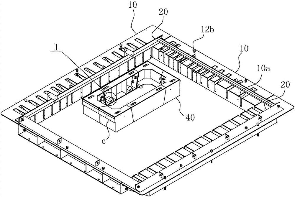
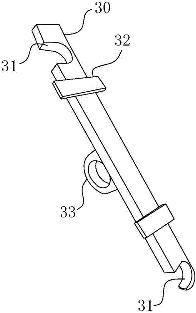
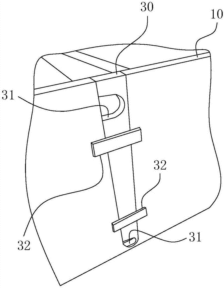
[0050] For ease of understanding, the attached Figure 1-11 , the concrete structure and working mode of the present invention are further described as follows:

[0051] The specific structure of the present invention refers to figure 1 As shown, it comprises an inner leaf wall mould, a window opening mold 40 for placement in the mold cavity of the inner leaf wall mould, and an outer leaf wall mold at the top face of the inner leaf wall mould. When in use, the window hole mold 40 is the same as the inner leaf wall mold, and is placed horizontally on a certain mold surface, and the mold surface is referred to as "base surface" here. The "vertical direction" described later refers to the direction perpendicular to the base plane. When the window hole mold 40 is integrated with the inner leaf wall mold as figure 1 When shown on the base surface, the space between the window hole mold 40 and the inner leaf wall mold forms a "back" shaped groove-like inner leaf wall pouring area...


PUM


Abstract

The invention belongs to the technical field of building products, and particularly relates to a PC wallboard mold and an integral mold-in method using the same. The PC wallboard mold comprises four inner wall side molds and positioning pieces. U-shaped positioning grooves are formed in the mold cavity surfaces of the inner wall side molds in a recessed mode. Positioning arc grooves are formed in the long edge sides of the positioning pieces in a recessed mode. The positioning pieces are fixedly inserted into the corresponding U-shaped positioning grooves. The PC wallboard mold has the advantages that mold disassembly is simple, operation is easy, convenient and fast, and manufacturing cost is low; and prefabrication and integral mold-in operation of a steel reinforcement framework can be achieved, and the manufacturing efficiency of a prefabrication wall body can be greatly improved. The invention further provides the integral mold-in method which is used for specially implementing the manufacturing process of the prefabrication wall body. The method includes the steps that the steel reinforcement framework matched with an inner wall mold cavity is prefabricated; reinforcing steel bars at the ends of the steel reinforcement framework are correspondingly clamped into the U-shaped positioning grooves; and the positioning arc grooves of all the positioning pieces are clamped into the corresponding reinforcing steel bars at the ends of the steel reinforcement framework one by one, and the positioning pieces are made to enter U-shaped positioning groove cavities.

Description

technical field [0001] The invention belongs to the technical field of building products, and in particular relates to a PC wall board mold and an integral molding method using the mold. Background technique [0002] In recent years, with the development of the economy, the construction industry has paid more and more attention to energy consumption and environmental pollution. The construction of traditional reinforced concrete structures in the field of construction often adopts on-site wet work. This construction method not only consumes a lot of wood as the bottom formwork and supporting materials, but also consumes a lot of energy, low construction efficiency, and long construction time. Noise and dust are produced, and at the same time, there is great pollution to the surrounding environment. Therefore, in recent years, the construction field has begun to introduce the concept of modular houses. Modular houses are different from traditional house construction. Usuall...

Claims


Application Information

Patent Timeline
IPC IPC(8): B28B7/18B28B23/02
CPCB28B7/0002B28B7/0014B28B7/186B28B23/022
Inventor 高君周治勺何云峰谢其阳陈彩凤
Owner ANHUI BAOYE CONSTR ENG GRP CO LTD
Learn More