
Pipe gallery working device

A technology of working device and pipe gallery, which is applied in water conservancy projects, artificial islands, underwater structures, etc., can solve problems such as low excavation efficiency and reduced excavation efficiency.

Pending Publication Date: 2017-10-20
CHINA RAILWAY CONSTR HEAVY IND
View PDF10 Cites 3 Cited by
  • Summary
  • Abstract
  • Description
  • Claims
  • Application Information

AI Technical Summary

Problems solved by technology

[0003] When the current pipe gallery operation device excavates the face, it usually uses a single excavating head to excavate according to the preset excavation direction. The lifting device is used to lift the muck out, which further reduces the overall excavation efficiency

Method used


Image

  • Pipe gallery working device
  • Pipe gallery working device
  • Pipe gallery working device

Examples


Embodiment Construction

[0035] The following will clearly and completely describe the technical solutions in the embodiments of the present invention with reference to the accompanying drawings in the embodiments of the present invention. Obviously, the described embodiments are only some, not all, embodiments of the present invention. Based on the embodiments of the present invention, all other embodiments obtained by persons of ordinary skill in the art without making creative efforts belong to the protection scope of the present invention.

[0036] The core of the present invention is to provide a pipe gallery operation device, which can improve the excavation efficiency.

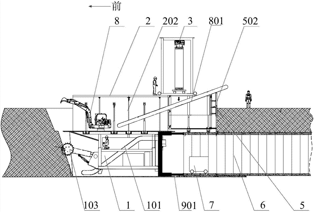
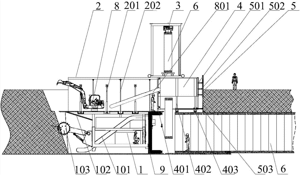
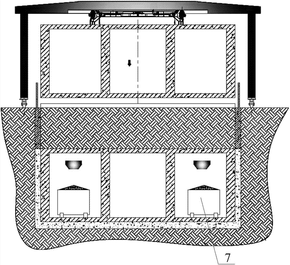
[0037] Please refer to Figure 1 to Figure 3 , figure 1 It is a schematic diagram of the advancing process of the synchronous construction of the upper and lower excavation devices of the pipe gallery operation device provided by the present invention; figure 2 It is a schematic diagram of pipe joint installation for synchro...


PUM


Abstract

The invention discloses a pipe gallery working device. The pipe gallery working device comprises a lower tunneling device, an upper tunneling device, a first conveying device, a soil blocking device and a second conveying device, wherein the upper tunneling device is used for being arranged at the top of the lower tunneling device; the first conveying device is used for conveying waste soil excavated by the lower tunneling device to a preset area; the first conveying device is arranged on the lower tunneling device; the soil blocking device is used for blocking a backfilling area at the rear part; the second conveying device is used for conveying waste soil excavated by the upper tunneling device to the backfilling area at the rear part; the second conveying device is rotatably connected to the upper tunneling device; and the tail part of the second conveying device is arranged at the top of the soil blocking device in an overlapping manner. According to the pipe gallery working device, the two parts, namely the upper tunneling device and the lower tunneling device can excavate the tunnel face simultaneously, so that the excavating efficiency is greatly improved; after excavating, the lower tunneling device conveys the waste soil correspondingly through the first conveying device, and the upper tunneling device directly conveys the waste soil to the backfilling area at the rear part through the second conveying device, and therefore the excavating efficiency is further improved.

Description

technical field [0001] The invention relates to the technical field of pipe gallery construction, in particular to a pipe gallery operation device. Background technique [0002] According to the buried depth of the comprehensive pipe gallery, there are open-cut method and underground excavation method. The construction method to choose depends on the ground conditions (such as traffic, construction, etc.), geological conditions and the buried depth of the pipe gallery. Excavation tools usually use pipe gallery operation devices. [0003] When the current pipe gallery operation device excavates the face, it usually uses a single excavating head to excavate according to the preset excavation direction. Lifting device carries out the slag is lifted out, thereby has further reduced whole excavation efficiency. [0004] Therefore, how to improve the excavation efficiency is a technical problem that those skilled in the art need to solve at present. Contents of the invention ...

Claims


Application Information

Patent Timeline
IPC IPC(8): E02D29/045
CPCE02D29/045
Inventor 刘飞香程永亮彭正阳唐崇茂张瑞临刘学马龙明周帅华申鹏飞
Owner CHINA RAILWAY CONSTR HEAVY IND
Learn More