Pump body component of dehumidifier, dehumidifier and control method of dehumidifier

A control method and technology for dehumidifiers, which are applied in pump control, pump components, components of pumping devices for elastic fluids, etc., can solve the problems that affect the overall performance of the dehumidifier, the quick joints are easily damaged, and the structure is complex. To achieve the effect of simple structure, easy maintenance and improved performance

Active Publication Date: 2017-10-20
GD MIDEA AIR-CONDITIONING EQUIP CO LTD
View PDF6 Cites 1 Cited by
  • Summary
  • Abstract
  • Description
  • Claims
  • Application Information

AI Technical Summary

Problems solved by technology

In the above technical solution, a quick connector needs to be installed in the water tank to communicate with the pump body components, which has a complex structure and high cost
Moreover, after long-term use, the quick connector is easily damaged and the water tank leaks, which affects the overall performance of the dehumidifier

Method used


Image

  • Pump body component of dehumidifier, dehumidifier and control method of dehumidifier
  • Pump body component of dehumidifier, dehumidifier and control method of dehumidifier
  • Pump body component of dehumidifier, dehumidifier and control method of dehumidifier

Examples


Embodiment Construction

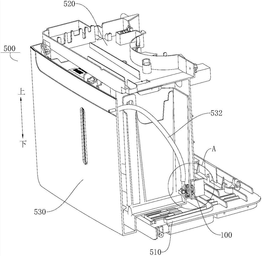
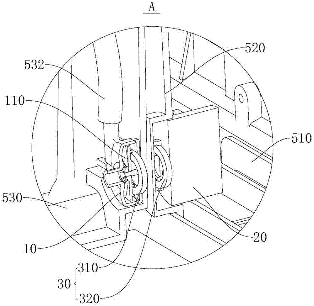
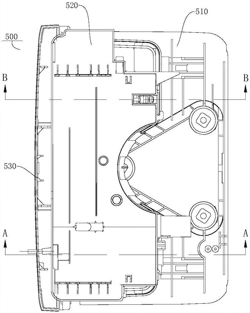
[0036] Embodiments of the present invention are described in detail below, examples of which are shown in the drawings, wherein the same or similar reference numerals designate the same or similar elements or elements having the same or similar functions throughout. The embodiments described below by referring to the figures are exemplary only for explaining the present invention and should not be construed as limiting the present invention.

[0037] In describing the present invention, it is to be understood that the terms "upper", "lower", "front", "rear", "left", "right", "vertical", "horizontal", "top", The orientation or positional relationship indicated by "bottom", "inner", "outer", etc. is based on the orientation or positional relationship shown in the drawings, and is only for the convenience of describing the present invention and simplifying the description, rather than indicating or implying the referred device or positional relationship. Elements must have certai...


PUM


Abstract

The invention discloses a pump body component of a dehumidifier, the dehumidifier and a control method of the dehumidifier. The dehumidifier comprises a water tank. The pump body component comprises a pump body, a driving motor and a magnetic piece; the pump body comprises an impeller and is located in the water tank; the driving motor is arranged outside the water tank; the magnetic piece is located between the pump body and the driving motor; and the driving motor drives the pump body to rotate through the magnetic piece. According to the pump body component of the dehumidifier, the pump body is arranged in the water tank, the driving motor is arranged outside the water tank, and the magnetic piece is arranged between the driving motor and the pump body, so that when the driving motor rotates, the pump body component can be driven through the magnetic piece to rotate, and water in the water tank can be pumped out. In addition, the magnetic piece is arranged between the driving motor and the pump body component for indirect driving, so that the problem of water leakage of the water tank due to the fact that a communicating hole is formed in the water tank is avoided. Besides, the driving motor is arranged outside the water tank, so that the driving motor is effectively prevented from being damaged by damp, and the driving motor is convenient to maintain and change.

Description

technical field [0001] The present invention relates to the technical field of household appliances, in particular to a pump body assembly of a dehumidifier, a dehumidifier and a control method thereof. Background technique [0002] During the working process of the dehumidifier, the moisture in the air condenses and drips into the water receiving tray when it passes through the evaporator of the dehumidifier. The water in the water receiving tray can flow into the water tank below from the outlet of the water receiving tray. When the water in the water tank is full, the user needs to dump it, which is cumbersome to operate. In the related art, a pump assembly is provided in the dehumidifier to pump the water in the water tank to the outside of the water tank. In the above technical solution, a quick joint needs to be provided in the water tank to communicate with the pump body assembly, which has a complicated structure and high cost. Moreover, after a long time of use, ...

Claims


Application Information

Patent Timeline
Patent Type & Authority Applications(China)
IPC IPC(8): F04D13/08F04D15/00F24F1/02F24F11/02
CPCF04D13/06F04D27/00F04D29/60F24F1/02
Inventor 张志明王晓宇
Owner GD MIDEA AIR-CONDITIONING EQUIP CO LTD
Why Eureka
Try Eureka