
Fuel sensor and fuel tank

A technology of fuel quantity sensor and end cap assembly, applied in the field of fuel quantity sensor, can solve problems such as fuel tank deformation, fire, aviation fuel leakage, etc., and achieve the effect of reducing strength

Active Publication Date: 2017-10-20
AVIC NANHANG SHENZHEN MEASUREMENT & CONTROL TECH
View PDF5 Cites 0 Cited by
  • Summary
  • Abstract
  • Description
  • Claims
  • Application Information

AI Technical Summary

Problems solved by technology

When the plane is in danger and crashes, the fuel tank is easily deformed due to the crash. The fuel level sensor will generate up and down pressure on the fuel level sensor due to its own structure and installation method. Piercing the fuel tank, causing aviation fuel to leak out, and then causing a fire hazard caused by the danger

Method used


Image

  • Fuel sensor and fuel tank
  • Fuel sensor and fuel tank
  • Fuel sensor and fuel tank

Examples


Embodiment Construction

[0029] The following will clearly and completely describe the technical solutions in the embodiments of the present invention with reference to the accompanying drawings in the embodiments of the present invention. Obviously, the described embodiments are only part of the embodiments of the present invention, not all of them. Based on the embodiments of the present invention, all other embodiments obtained by persons of ordinary skill in the art without creative efforts fall within the protection scope of the present invention.

[0030] It should be noted that all directional indications (such as up, down, left, right, front, back...) in the embodiments of the present invention are only used to explain the relationship between the components in a certain posture (as shown in the accompanying drawings). Relative positional relationship, movement conditions, etc., if the specific posture changes, the directional indication will also change accordingly.

[0031] In the present in...


PUM


Abstract

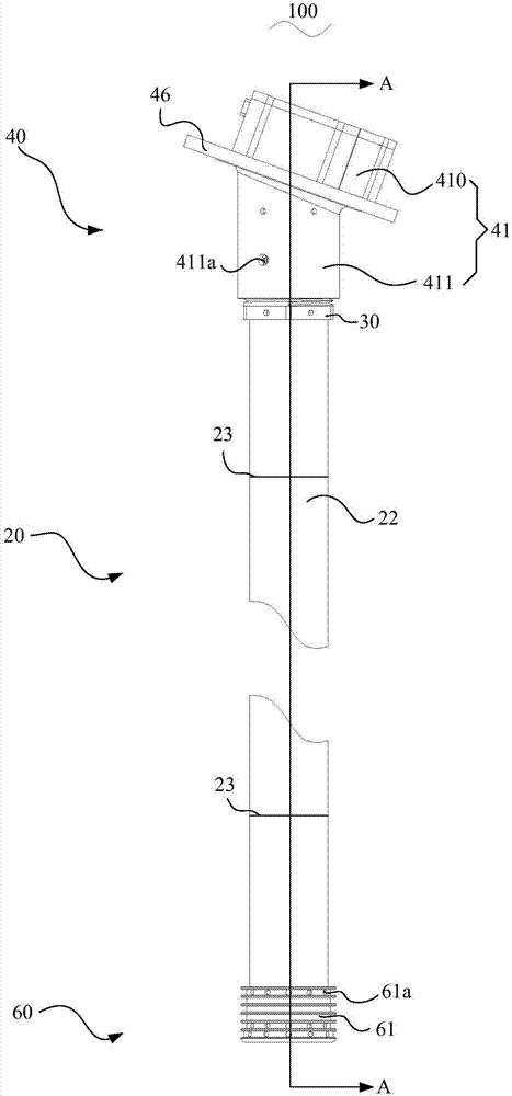
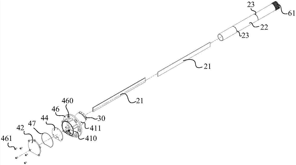
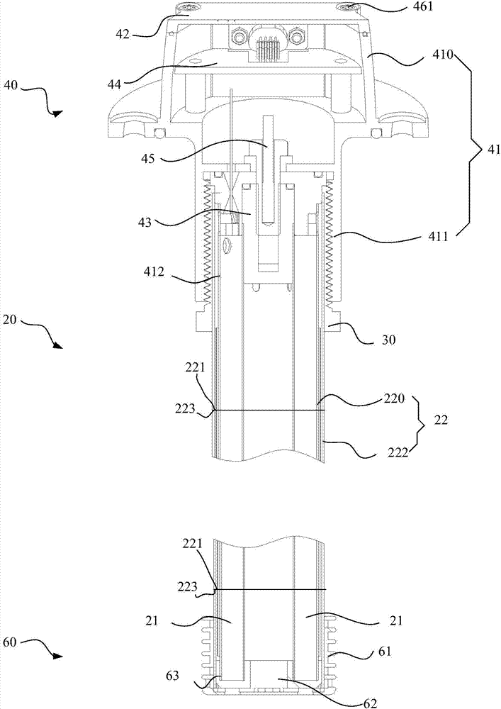
The invention provides a fuel sensor and a fuel tank. The fuel sensor comprises an electrode component and an end cover component and an insulation component which are connected to the two ends of the electrode component respectively; the electrode component comprises a pipe sleeve and two mutually parallel electrode plates contained in the pipe sleeve, and at least one first fold is arranged on the surface of the pipe sleeve. Accordingly, the fold structure is designed on the outer surface of the pipe sleeve on purpose, the local point strength of the fuel sensor can be lowered, the fuel senor subjected to the exogenic action in an emergency can adopt a passive measure to achieve the self-destruct function, and then the phenomenon that due to the fact that a fuel leak is caused due to the self structure of the fuel sensor, greater accidents are caused is prevented.

Description

technical field [0001] The invention relates to the field of oil quantity sensors, in particular to an oil quantity sensor and a fuel tank. Background technique [0002] Compared with the traditional float type oil quantity sensor, the capacitive oil quantity sensor in the prior art cancels the mechanical transmission mechanism, has compact structure, small volume, longer service life and greatly improved accuracy. The working principle of the capacitive sensor is based on Cylindrical capacitors work on the principle. The capacitor is composed of two insulated coaxial cylindrical plates with an inner electrode and an outer electrode. When an electrolyte with a dielectric constant e is filled between the two cylinders, the capacitance between the two cylinders C = 2πeL / lnD / d, where L is the length of the overlapping part of the two cylinders; D is the diameter of the outer cylinder electrode; d is the diameter of the inner cylinder electrode; e is the dielectric constant of t...

Claims


Application Information

Patent Timeline
Patent Type & Authority Applications(China)
IPC IPC(8): G01F23/26
CPCG01F23/263
Inventor 田晓理陈鲲贺巧喜
Owner AVIC NANHANG SHENZHEN MEASUREMENT & CONTROL TECH
Learn More