Multifunctional remote control device for operation in vacuum tank and narrow area

A remote control device and multi-functional technology, applied in the field of remote control, can solve problems such as low efficiency, difficult cleaning, narrow space, etc., to achieve the effects of reducing the decline in service life, removing stubborn stains, and compressing preparation time

Active Publication Date: 2017-10-20
BEIJING INST OF ENVIRONMENTAL FEATURES
View PDF9 Cites 3 Cited by
  • Summary
  • Abstract
  • Description
  • Claims
  • Application Information

AI Technical Summary

Problems solved by technology

[0003] The vacuum tank is a device for extracting vacuum. Before the vacuuming operation, the inside of the tank must be wiped with oil and cleaned. During vacuum operation, oil molecules will cause irreparable damage to the molecular pump in the vacuum tank; while the tank body of the vacuum tank is composed of heat sink A, outer wall B and pneumatic motor, such as figure 1 However, in the tank body of the vacuum tank, personnel can enter the area, and can carry out quick and effective cleaning; and for the interlayer between the heat sink and the outer wall inside the vacuum tank, this space also needs to be completely cleaned, but Due to the narrow space here, it is difficult to carry out effective cleaning
[0004] Nowadays, because the interlayer space is too narrow, personnel cannot clean it conveniently. They often use the method of tying a cloth belt to the head of the long pole and wiping it repeatedly. However, this cleaning is not only inefficient, but also because the actual cleaning cannot be observed. Sometimes it is not guaranteed to be cleaned cleanly, and due to the high height of the parts above the vacuum tank, personnel cannot clean it safely, which poses a safety hazard; and this problem also exists in many narrow areas

Method used


Image

  • Multifunctional remote control device for operation in vacuum tank and narrow area
  • Multifunctional remote control device for operation in vacuum tank and narrow area
  • Multifunctional remote control device for operation in vacuum tank and narrow area

Examples


Embodiment Construction

[0029] The following describes the exemplary embodiments of the present invention in detail with reference to the accompanying drawings; the description of the exemplary embodiments is only for the purpose of illustration, and is by no means limiting the present invention and its application or use.

[0030] Because the interlayer between the heat sink and the outer wall of the vacuum tank is too narrow, personnel cannot clean it safely. The efficiency of repeated cleaning by tying the head of a long pole to a cloth belt is too low, and it is impossible to observe the actual cleaning situation. Ensure that it is cleaned cleanly. Once stains and oil stains appear inside the tank, it is easy to cause irreparable damage to the molecular pump in the vacuum tank. Therefore, a remote control device that can work in a narrow area is needed to carry out cleaning operations.

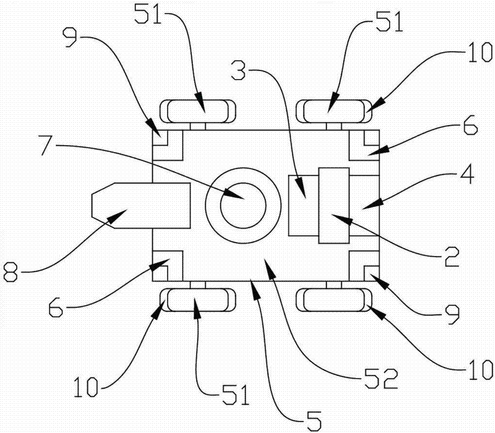
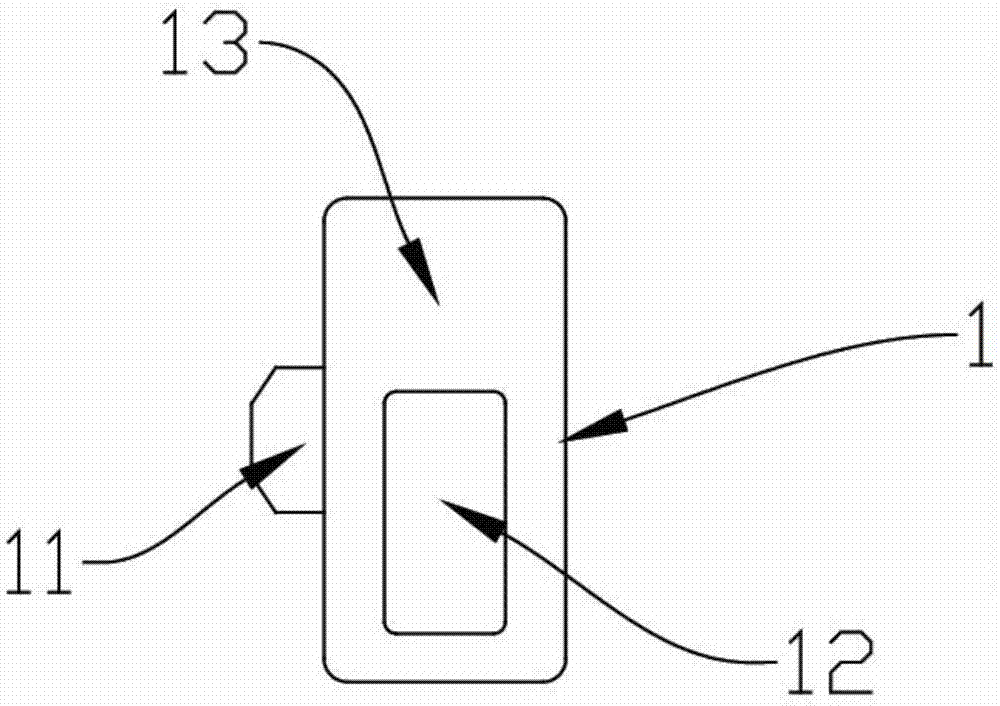
[0031] In this embodiment, the multifunctional remote control device consists of a remote control 1 and a remot...


PUM


Abstract

The invention discloses a multifunctional remote control device for operation in a vacuum tank and a narrow area. The multifunctional remote control device includes a remote controller for remote control and a remotely controlled dolly. The remotely controlled dolly comprises a motion platform module including a platform body for mounting functional modules and wheels disposed on both sides of the platform body and equipped with erasing tires. The platform body is also provided with a control system module for receiving the operation commands of the remote controller and controlling the execution of the remotely controlled dolly. The functional modules comprise an energy module for controlling the remotely controlled dolly to be adsorbed on the surface of the narrow area, a magnetic adsorption module for changing the adsorption state of the remotely controlled dolly, a cleaning module, and a regional pressure adjustment module installed in the corner regions on the platform body and capable of changing the pressure of respective regions. The remote controller remotely controls the remotely controlled dolly to perform cleaning operations so as to remove stubborn stains, improve cleaning efficiency, compress test preparation time, and suppress a decrease in the service lives of various devices within the vacuum tank caused by oil stains.

Description

technical field [0001] The invention relates to the field of remote control, in particular to a multifunctional remote control device for working in vacuum tanks and narrow areas. Background technique [0002] The technical background related to the present invention will be described below, but these descriptions do not necessarily constitute the prior art of the present invention. [0003] The vacuum tank is a device for extracting vacuum. Before the vacuuming operation, the inside of the tank must be wiped with oil and cleaned. During vacuum operation, oil molecules will cause irreparable damage to the molecular pump in the vacuum tank; while the tank body of the vacuum tank is composed of heat sink A, outer wall B and pneumatic motor, such as figure 1 However, in the tank body of the vacuum tank, personnel can enter the area, and can carry out quick and effective cleaning; and for the interlayer between the heat sink and the outer wall inside the vacuum tank, this space...

Claims


Application Information

Patent Timeline
Patent Type & Authority Applications(China)
IPC IPC(8): G05D1/02G08C17/02
CPCG05D1/0214G05D1/0253G05D1/0259G05D2201/02G08C17/02
Inventor 王云强张广万继敏李学智郭聚光张尚
Owner BEIJING INST OF ENVIRONMENTAL FEATURES
Why Eureka
Try Eureka