
A kind of drilling method of porous copper ingot for niobium-three-tin superconducting wire

A technology of superconducting wire and drilling method, which is applied in the usage of superconducting elements, superconducting devices, superconducting/high-conducting conductors, etc. It can solve the problems of small spacing and poor deformation of core wires, and achieve reduction in quantity, Improve the effect of poor deformation and optimize distribution

Active Publication Date: 2019-08-20
西部超导材料科技股份有限公司
View PDF2 Cites 0 Cited by
  • Summary
  • Abstract
  • Description
  • Claims
  • Application Information

AI Technical Summary

Problems solved by technology

[0004] The purpose of the invention is to provide a method for drilling holes in porous copper ingots for niobium-three-tin superconducting wires, which solves the problems of Nb prepared by using existing porous copper ingots. 3 The problem of overlapping core wires caused by poor deformation of the outer core wires of the subcomponents in the Sn superconducting wire and too small spacing

Method used


Image

  • A kind of drilling method of porous copper ingot for niobium-three-tin superconducting wire

Examples


Embodiment 1

[0021] Step 1, select an oxygen-free copper rod with a diameter of Φ200mm, and saw and cut it to obtain an oxygen-free copper ingot with a length of 300mm;

[0022] In step 2, the oxygen-free copper ingot obtained in step 1 is clamped on a lathe, and the end surface is processed to be smooth. Use the method of deep hole drilling to drill 2 layers of through holes from one end, the diameter of the innermost layer is Φ14mm, and the diameter of the outermost layer is Φ25mm, and the number of holes in each layer is the same as 20, which are radially distributed.

Embodiment 2

[0024] Step 1, select an oxygen-free copper rod with a diameter of Φ250mm, and cut it to obtain an oxygen-free copper ingot with a length of 800mm;

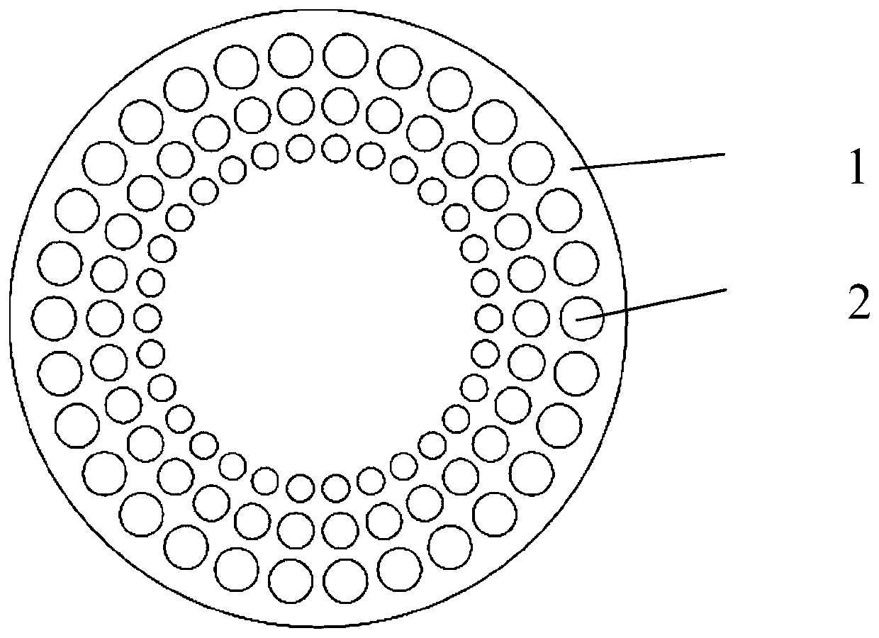
[0025] In step 2, the oxygen-free copper ingot obtained in step 1 is clamped on a lathe, and the end surface is processed to be smooth. Use the method of deep hole drilling to drill 3 layers of through holes from one end, the diameter of the innermost layer is Φ10mm, the diameter of the outermost layer is Φ20mm, and the number of holes in each layer is the same as 30, which are radially distributed. The cross-section of the prepared porous copper ingot, such as figure 1 shown.

Embodiment 3

[0027] Step 1, select an oxygen-free copper rod with a diameter of Φ300mm, and cut it to obtain an oxygen-free copper ingot with a length of 500mm;

[0028] In step 2, the oxygen-free copper ingot obtained in step 1 is clamped on a lathe, and the end surface is processed to be smooth. Use deep hole drilling method to drill 4 layers of through holes from one end, the diameter of the innermost layer is Φ8mm, the diameter of the outermost layer is Φ15mm, the number of holes in each layer is the same as 50, and they are radially distributed.


PUM

PropertyMeasurementUnit
diameteraaaaaaaaaa
lengthaaaaaaaaaa
diameteraaaaaaaaaa

Abstract

The invention discloses a drilling method of a porous copper ingot for a Nb3Sn superconducting wire. An oxygen-free copper rod is sawed to obtain an oxygen-free copper ingot. The oxygen-free copper ingot is clamped on a lathe, and the end surfaces are machined to be flat. A deep hole drilling method is used to drill multi-layer through holes from one end. The diameters of the through holes increase layer by layer, the diameter of the innermost layer through holes is the smallest, the diameter of the outermost layer through holes is the biggest, the number of the holes in each layer is the same, and the through holes are distributed radially. Thus the ingot is obtained. The method optimizes the distribution of the holes in the porous copper ingot, reduces the number of outermost layer through holes, increases the diameters of the holes and the spacing between the holes, ensures the same number of drilling holes in each layer and consistent spacing between the holes of each layer, and thus solves the problem that superconducting wires prepared by methods in the prior art do not perform well in deformation and have too small spacing which causes core wire lapping after heat treatment.

Description

technical field [0001] The invention belongs to the technical field of superconducting material processing, and in particular relates to a drilling method for a porous copper ingot used for a niobium-three-tin superconducting wire. Background technique [0002] The inner tin method is the current preparation of Nb 3 One of the most important methods for Sn superconducting wires, which usually adopts multiple composite methods, is to put Nb rods into porous copper ingots and extrude CuNb composite rods, and then put Sn rods into the drilled CuNb composite rods Processing to obtain subcomponents, and finally multiple subcomponents are compounded and stretched to obtain Nb 3 Sn superconducting wire. The Cu / Nb / Sn ratio in the superconducting wire can be changed through the design of the porous copper ingot, thereby improving the performance of the final wire. [0003] Currently Nb 3 Porous copper ingots for Sn superconducting wires are usually distributed uniformly in multip...

Claims


Application Information

Patent Timeline
Patent Type & Authority Patents(China)
IPC IPC(8): H01B13/00H01B12/10
CPCH01B12/10H01B13/00Y02E40/60
Inventor 史一功张科刘建伟李建峰刘向宏冯勇
Owner 西部超导材料科技股份有限公司
Learn More