Rubber gun and driving device thereof

A transmission device and driving device technology, applied in the field of glue guns, can solve the problems of loss of transmission force, affecting the service life of the lead screw nut, complex transmission structure, etc., and achieve the effects of reliable clutch transmission, convenient glue operation, and reliable transmission.

Active Publication Date: 2017-10-24
柏永茂
View PDF8 Cites 10 Cited by
  • Summary
  • Abstract
  • Description
  • Claims
  • Application Information

AI Technical Summary

Problems solved by technology

[0004] Although the glue gun can realize the extrusion of glass glue and the clutch between the lead screw and the nut, the top of the thread of the lead screw is sharp, and the twitching of the lead screw back and forth for a long time will cause the top to wear
In turn, the deep and shallow groove wear becomes lost or weakened the original clutch function, or even loses the original clutch function, and the most serious can lead to the loss of the transmission force.
Moreover, since the limit plane is set on the outer periphery of the screw, it is completely different from the structure of the original screw nut with the most stable quality, so that the balls cannot circulate in it, which will seriously affect the service life of the screw nut.
The glue gun has a lot of parts, the processing is relatively complicated, and the cost of the parts is high. During the processing of deep and shallow grooves, it is easy to produce high unqualified, resulting in unreliable clutch and transmission of the screw nut. The structure can allow a relatively small number of balls to be set Less, and problems such as processing accuracy, resulting in a greatly reduced thrust, only about 1200N, which cannot meet the requirements of the glue gun
[0005] To sum up, how to solve the problems of complex transmission structure, unreliable transmission and small thrust of the existing glue gun has become a problem to be solved urgently by those skilled in the art

Method used


Image

  • Rubber gun and driving device thereof
  • Rubber gun and driving device thereof
  • Rubber gun and driving device thereof

Examples


Embodiment Construction

[0056] The core of the present invention is to provide a transmission device for a glue gun, which simplifies the transmission structure, improves the transmission reliability and increases the thrust.

[0057] The invention also provides a glue gun using the transmission device, which simplifies the transmission structure, improves the transmission reliability and increases the thrust.

[0058] The following will clearly and completely describe the technical solutions in the embodiments of the present invention with reference to the accompanying drawings in the embodiments of the present invention. Obviously, the described embodiments are only some, not all, embodiments of the present invention. Based on the embodiments of the present invention, all other embodiments obtained by persons of ordinary skill in the art without making creative efforts belong to the protection scope of the present invention.

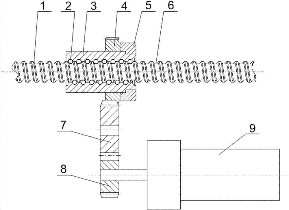
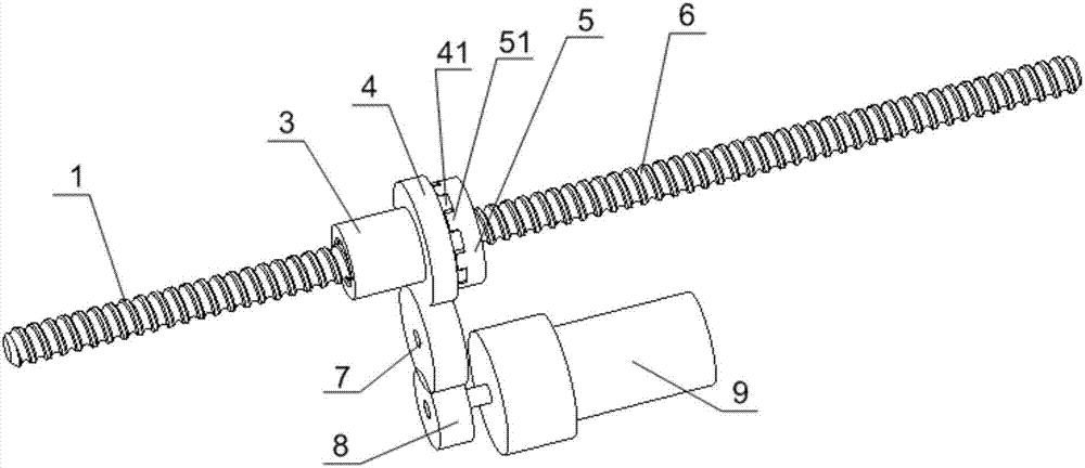
[0059] Please refer to figure 1 and figure 2 , the present invention ...


PUM


Abstract

The invention discloses a rubber gun and a driving device thereof. The driving device of the rubber gun comprises a lead screw, a nut and a first gear, the nut is matched with the lead screw, and balls are arranged between the lead screw and a thread groove of the nut; the periphery of the nut is sleeved with the first gear in a sliding mode, the first gear is connected with the nut in a clutch mode, and a driving tooth used for being connected with the driving device in a driving mode is arranged on the periphery of the first gear. The driving device keeps a complete lead-nut mechanism, is simple in structure, and is provided with few parts; the balls will not fall off from the thread groove and also will not get stuck; the lead screw can move in the front-back direction, power transmission is reliable, large thrust can be provided, and reliable clutch driving can be achieved.

Description

technical field [0001] The invention relates to the technical field of glue guns, in particular to a transmission device for glue guns. It also relates to a glue gun using the transmission device. Background technique [0002] Glue guns are used for gluing. Existing glue guns mainly include casing, glue barrel, push rod and driving device. The glue barrel is installed on the casing, and the front end of the push rod is provided with an end plate. In the barrel, glass glue is put into the glue barrel, and the driving device drives the push rod to move along the axial direction of the glue barrel, and then pushes the glass glue to extrude from the front end of the glue barrel. [0003] The push rod and driving device of an existing glue gun adopt a screw nut structure as a source of transmission and thrust generation. It mainly includes a screw, a nut and a ball. The screw passes through the nut. There are deep and shallow grooves on the nut. The ball is located in the nut a...

Claims


Application Information

Patent Timeline
Patent Type & Authority Applications(China)
IPC IPC(8): B05C17/005B05C5/00
CPCB05C5/00B05C17/005
Inventor 柏永茂柏金霞柏妍萱
Owner 柏永茂
Why Eureka
Try Eureka