Assembled reinforced concrete framework structure beam-column joint and manufacturing method thereof

A technology of reinforced concrete and beam-column joints, which is applied in the field preparation of building components, building construction, formwork/template/work frame, etc. The effect of application value, good anchorage, simple and practical construction method

Active Publication Date: 2017-10-24
姚伟华 +1
View PDF8 Cites 14 Cited by
  • Summary
  • Abstract
  • Description
  • Claims
  • Application Information

AI Technical Summary

Problems solved by technology

[0014] The purpose of the present invention is to overcome the deficiencies of the prior art, aiming at the longitudinal bars of the frame beams at the joints of prefabricated reinforced concrete frame beams and columns that are not anchored in a straight line into the frame columns until the frame beams of the adjacent spans, the longitudinal bars of the frame beams are anchored In order to solve the problem of poor stability, improve the design of the connection between the frame nodes and the surrounding fram...

Method used


Image

  • Assembled reinforced concrete framework structure beam-column joint and manufacturing method thereof
  • Assembled reinforced concrete framework structure beam-column joint and manufacturing method thereof
  • Assembled reinforced concrete framework structure beam-column joint and manufacturing method thereof

Examples


Embodiment 1

[0062] Such as figure 1 As shown, a beam-column node of an assembled reinforced concrete frame structure of the present invention is composed of a splicing node 13 of a prefabricated frame column 11 and a prefabricated frame beam 12 and a cast-in-place concrete 14. The column longitudinal reinforcement 131 in the prefabricated frame column 11 is formed from The top of the prefabricated frame column 11 protrudes to form the reserved longitudinal reinforcement 1311 at the top of the column; a number of node column stirrups 132 are arranged along the periphery of the reserved longitudinal reinforcement 1311 at the top of the column, and are bound with the reserved longitudinal reinforcement 1311 at the top of the column; the prefabricated frame The beam 12 is spliced ​​on the top of the prefabricated frame column 11, and the beam bottom longitudinal reinforcement 133 in the prefabricated frame beam 12 protrudes toward the direction of the splicing joint of the prefabricated frame ...
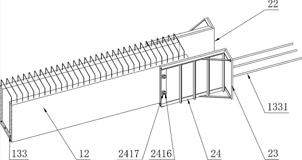
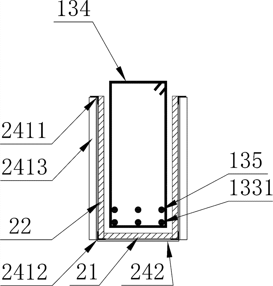
Embodiment 2

[0064] Such as figure 2 Shown, the manufacturing mold of a kind of prefabricated reinforced concrete frame structure beam-column node of the present invention comprises splicing joint bottom formwork 21, splicing joint side formwork 22, node corner formwork 23 and the fixed steel frame 24 of fixing above-mentioned formwork; The fixed steel frame 24 fixes and splices the joint bottom formwork 21 and the joint side formwork 22 into a U-shaped groove structure, and splices the node corner formwork 23 and the joint side formwork 22 at right angles, and together constitutes the pouring space of the beam-column joint . Such as Figure 4 As shown, when in use, the mold is encased in the prefabricated frame beam 12, the outer mold pull rod 2416 is used to pass through the bolt mounting hole 2419, and the rod fastener 2417 is firmly fixed to the beam end of the prefabricated frame beam 12.
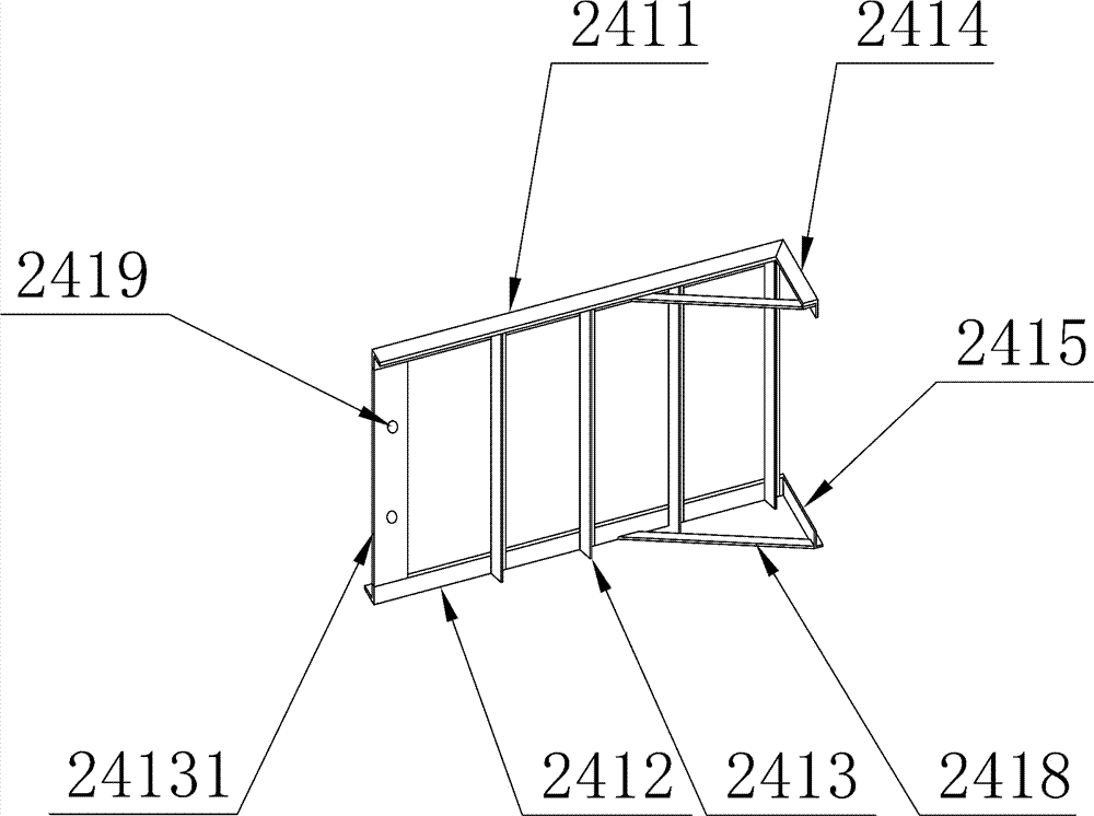
Embodiment 3

[0066] Such as Figure 2-4 As shown, a manufacturing mold of a beam-column joint of an assembled reinforced concrete frame structure of the present invention, on the basis of Embodiment 2, the fixed steel frame 24 includes two plane trusses 241 and bottom bars 242; the plane truss 241 comprises side mold upper chord 2411, side mold lower chord 2412, vertical web 2413, angle mold upper chord 2414, angle mold lower chord 2415; described side mold upper chord 2411, side mold lower chord 2412 angle mold upper chord 2414 1. The lower chord 2415 of the angle mold is made of angle steel; among the vertical webs 2413, the end vertical web 24131 far away from the upper chord 2414 of the angle mold and the lower chord 2415 of the angle mold is made of steel slats, and the other vertical webs 2413 are all made of angle steel; the upper chord 2411 of the side form is parallel to the lower chord 2412 of the side form, and is vertically fixedly connected with the two ends of the vertical we...


PUM


Abstract

The invention relates to an assembled reinforced concrete framework structure beam-column joint and a manufacturing method thereof, and belongs to the technical field of building materials and building construction. The assembled reinforced concrete framework structure beam-column joint is composed of a splicing joint (13) of a prefabricated framework column (11) and a prefabricated framework beam (12), and cast-in-place concrete (14). Column longitudinal ribs (131) in the prefabricated framework column (11) extend out of the top of the column to form column top reserved longitudinal ribs (1311). A plurality of joint column hoops (132) are arranged around the column top reserved longitudinal ribs (1311) and bound to the column top reserved longitudinal ribs (1311). The prefabricated framework beam (12) is spliced to the top of the prefabricated framework column (11). A beam bottom longitudinal rib (133) in the prefabricated framework beam (12) extends out towards the splicing head of the prefabricated framework beam (12), and penetrates through the splicing joint (13) to be linearly anchored. According to the assembled reinforced concrete framework structure beam-column joint and the manufacturing method thereof, the design of connection of a framework joint and a framework beam column around the framework joint is modified, linear anchoring of the framework beam bottom longitudinal rib and continuous through anchoring of a framework beam top longitudinal rib are achieved, connection integrity of an assembled reinforced concrete framework structure is enhanced, and the assembled reinforced concrete framework structure can possess better earthquake-resistant ductility.

Description

technical field [0001] The invention belongs to the technical field of building materials and building construction, and relates to an assembled reinforced concrete frame structure beam-column node and a manufacturing method thereof. Background technique [0002] Prefabricated concrete structures refer to concrete structures assembled by prefabricated concrete components through reliable connection methods, including assembled integral concrete structures, fully assembled concrete structures, etc. In construction engineering, it is referred to as prefabricated building; in structural engineering, it is referred to as prefabricated structure. Prefabricated components refer to concrete components prefabricated in factories or on site, such as beams, slabs, walls, columns, balconies, stairs, canopies, etc. [0003] Traditional building construction technology has low production efficiency, slow construction speed, long construction period, high material consumption and high la...

Claims


Application Information

Patent Timeline
IPC IPC(8): E04B1/21E04G13/00
CPCE04B1/21E04G13/00
Inventor 姚芳辉姚伟华
Owner 姚伟华
Why Eureka
Try Eureka