Miniature hydraulic drive system used for ankle joint artificial limb

A driving system and ankle joint technology, applied in fluid pressure actuation devices, accumulator devices, artificial legs, etc., can solve problems such as slow response speed and insufficient output torque, so as to avoid start-stop and commutation, Reduced power consumption, the effect of reducing peak power requirements

Inactive Publication Date: 2017-10-24
BEIHANG UNIV
View PDF7 Cites 9 Cited by
  • Summary
  • Abstract
  • Description
  • Claims
  • Application Information

AI Technical Summary

Problems solved by technology

Most of the existing ankle prostheses use motor-driven models, but motor-driven ankle prostheses have the disadvantages of slow response and insufficient output torque.

Method used


Image

  • Miniature hydraulic drive system used for ankle joint artificial limb
  • Miniature hydraulic drive system used for ankle joint artificial limb
  • Miniature hydraulic drive system used for ankle joint artificial limb

Examples


Embodiment

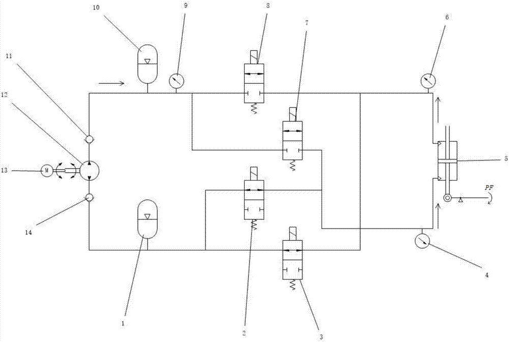
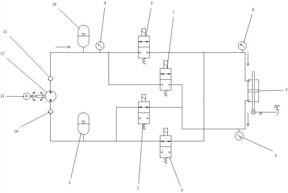
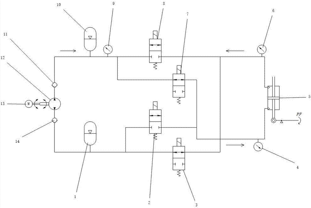
[0029] In the present invention, the hydraulic pump 12 adopts the electric motor 13 (brushless DC motor) to control the plunger pump, and the oil outlet of the hydraulic pump 12 passes through the first one-way valve 11 and the first accumulator 10, the first pressure sensor 9, the first The two normally closed switch valves 8 and the first normally closed switch valve 7 are connected; the oil inlet of the hydraulic pump 12 is connected with the second accumulator 1, the first normally open switch valve 2 and the second normally open switch valve 1 through the second check valve 14. Open the switch valve 3 to connect. The upper rod cavity of the double rod hydraulic cylinder 5 is connected with the second pressure sensor 6 , the second normally closed switch valve 8 and the second normally open switch valve 3 . The lower rod chamber of the double-rod hydraulic cylinder 5 is connected with the third pressure sensor 4 , the first normally closed switch valve 7 and the first norm...


PUM


Abstract

The invention discloses a miniature hydraulic drive system used for an ankle joint artificial limb. The miniature hydraulic drive system comprises an electromotor, a hydraulic pump, a first check valve, a second check valve, a first energy accumulator, a second energy accumulator, a first normally-opened switching valve, a second normally-opened switching valve, a first normally-closed switching valve, a second normally-closed switching valve and a double-ejection-rod hydraulic cylinder. In the miniature hydraulic drive system, by means of unceasing work of the motor and energy storage of the energy accumulators, the requirement for the peak power of the motor can be reduced; and the power consumption is lowered during long-term walking so that the cruising ability can be improved. In the miniature hydraulic drive system, the direct-current motor and the hydraulic pump unceasingly work in the whole movement process, the energy utilization efficiency of the system is improved, frequent start, stop and reversing of the motor are avoided, and therefore the usability of the motor is improved, and the service life of the motor is prolonged.

Description

technical field [0001] The invention relates to the technical field of prosthetics and orthotics, and relates to a hydraulic circuit system of low power consumption ankle joint prostheses combined active and passive. Background technique [0002] In today's society, due to traffic accidents, diseases and other reasons, the number of below-knee amputations is gradually increasing, and the most common ways for lower limb amputee to compensate for their walking ability defects are wheelchairs, crutches and artificial limbs. Wheelchairs occupy a large area and are limited to places that wheeled machines cannot reach, such as walking on stairs. The use of crutches takes up the functions of both hands and reduces the physical function of the wearer. Wearing prosthetics can achieve compensation for the missing functions of the human body, and has advantages in terms of decoration and walking comfort. [0003] At present, there are many types of ankle joint prostheses, classified ...

Claims


Application Information

Patent Timeline
Patent Type & Authority Applications(China)
IPC IPC(8): F15B1/02F15B11/08F15B13/04A61F2/66
CPCA61F2/6607F15B1/024F15B11/08F15B13/021F15B13/04F15B2211/7053F15B2211/88
Inventor 王兴坚王玮群李如飞王少萍林长宏
Owner BEIHANG UNIV
Why Eureka
Try Eureka